
Solar battery component cover plate glass and solar battery component

A solar cell and cover glass technology, applied in the field of solar cells, can solve problems such as increased difficulty in solar energy, complex molds, and weak bonding, and achieve the effects of easy promotion and application, simple manufacturing process, and low battery leakage

Inactive Publication Date: 2012-05-09
DONGGUAN CSG SOLAR GLASS
View PDF4 Cites 2 Cited by
  • Summary
  • Abstract
  • Description
  • Claims
  • Application Information

AI Technical Summary

Problems solved by technology

However, in actual use, this smooth plane is not firmly bonded to the EVA layer, which may easily cause battery leakage; moreover, the embossed layer adopts a honeycomb pattern structure and the honeycomb mouth is a deformed regular hexagon. The structural mold is relatively complex, and there are edges and corners between each honeycomb structure. Since solar cell modules are mostly installed outdoors in harsh environments, this angular structure is likely to cause dust to accumulate on the surface of the solar cell module cover glass, making it difficult to clean
The above-mentioned patent achieves the problem of easy cleaning by coating the embossed layer of the glass substrate with a coating that can modify the glass and reduce the tension, but the thickness of the coating is only 130nm to 145nm, and the edges and corners between the honeycombs The structure still exists, even if the coating is added, it still makes the surface of the solar cell module cover glass easy to accumulate dust, and at the same time increases the process steps of manufacturing the cover glass, which virtually increases the cost of the solar cell module, thus making solar energy Increased difficulty in application, promotion and popularization

Method used


Image

  • Solar battery component cover plate glass and solar battery component
  • Solar battery component cover plate glass and solar battery component
  • Solar battery component cover plate glass and solar battery component

Examples


Embodiment 1

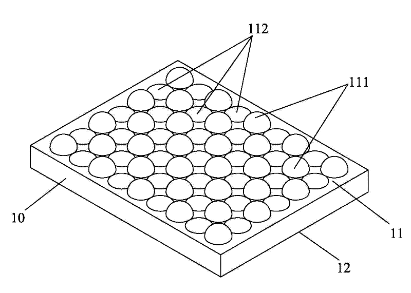
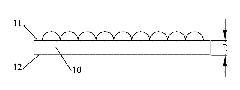
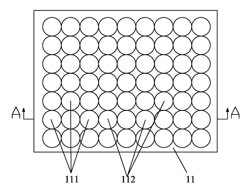
[0034] One of the specific implementations of a solar cell module cover glass of the present invention, such as figure 1 , figure 2 , image 3 and Figure 4As shown, a glass substrate 10 is included, wherein the glass substrate 10 has a first surface 11 and a second surface 12, the first surface 11 is arranged on the side facing the incident sunlight, and the second surface 12 is arranged on the side facing the solar cell module On one side of the EVA layer of the silicon wafer, the first surface 11 is provided with a pattern structure having hemispherical unit protrusions 111 and hemispherical unit depressions 112, and the second surface 12 is a suede structure. Wherein, the hemispherical unit depression 112 is a hemispherical hole surface. Specifically, the pattern structure is a pattern structure composed of hemispherical unit protrusions 111 and hemispherical unit depressions 112 arranged horizontally and vertically. Next to a hemispherical unit protrusion 111, so tha...

Embodiment 2

[0040] The second specific embodiment of a solar cell module cover glass of the present invention, such as Figure 5 and Figure 6 As shown, the main technical solution of this embodiment is the same as that of Embodiment 1, and the features not explained in this embodiment adopt the explanation in Embodiment 1, and will not be repeated here, and are described in Figure 5 and Figure 6 neutralize figure 1 , figure 2 , image 3 and Figure 4 The same parts bear the same reference numerals. The difference between this embodiment and Embodiment 1 is that the pattern structure is a pattern structure composed of hemispherical unit protrusions 111 and hemispherical unit recesses 112 arranged at intervals in the horizontal and vertical directions. That is, in the transverse direction, there is a certain distance between a hemispherical unit protrusion 111 and a hemispherical unit depression 112, and there is a certain distance between a hemispherical unit depression 112 and a...

Embodiment 3

[0042] The third specific embodiment of a solar cell module cover glass of the present invention, the main technical solution of this embodiment is the same as that of embodiment 1, and the features not explained in this embodiment are explained in embodiment 1, and are described in This will not be repeated here. The difference between this embodiment and Embodiment 1 is that the radius R of the hemispherical unit protrusion 111 is 0.5 mm˜1.9 mm, and the radius R of the hemispherical unit recess 112 is 0.5 mm˜1.9 mm.

[0043] Wherein, the radius R of the hemispherical unit protrusion 111 can be 0.5mm, 1.9mm, 1.7mm or 1mm, and the radius R of the hemispherical unit depression 112 can be 0.5mm, 1.9mm, 1.7mm or 1mm.

[0044] In addition, the hemispherical unit protrusion 111 and the hemispherical unit recess 112 may have the same radius length or different radius lengths.

[0045] Wherein, the thickness D of the glass substrate 10 may be 5.1 mm, 5.7 mm or 5.4 mm.


PUM


Abstract

The invention relates to solar battery component cover plate glass and a solar battery component. The solar battery component cover plate glass comprises a glass matrix provided with a first surface and a second surface, wherein the first surface is arranged on one side towards incident sunlight; the second surface is arranged on one side towards an ethylene-vinyl acetate copolymer (EVA) layer with a silicon chip of the solar battery component; the first surface has a patterned structure provided with hemispherical convex units and hemispherical concave units; and the second surface has a textured structure. The solar battery component is provided with the cover plate glass, the EVA layer with the silicon chip and a back board sequentially arranged from top to bottom, wherein the cover plate glass is the solar battery component cover plate glass. The solar battery component cover plate glass and the solar battery component can effectively reduce reflection rays incident on the solar battery component cover plate glass, further improve the light transmittance of the solar battery component, can not deposit dust easily, are easy to clean, and can be applied to the severe outdoor environment.

Description

technical field [0001] The invention relates to the technical field of solar cells, in particular to a solar cell component cover glass and a solar cell component. Background technique [0002] Solar cell module cover glass is also called solar glass cover, because solar cell module cover glass has the characteristics of high solar photoelectric conversion rate, low plate pressure damage rate, high strength and good flatness, it can fully transmit sunlight for solar energy The solar cell absorbs and protects the solar cell under it from being damaged by external wind, frost, rain, snow and other harsh weather or space operating conditions with its own strength. Therefore, it is widely used in various types and specifications of monocrystalline silicon wafers, Polycrystalline silicon wafers and solar cell modules of amorphous silicon wafers. [0003] At present, the structure of the commonly used solar cell module cover glass includes a surface with a smooth plane and a surf...

Claims


Application Information

Patent Timeline
Patent Type & Authority Patents(China)
IPC IPC(8): H01L31/048H01L31/052H01L31/0232H01L31/054
CPCY02E10/52Y02E10/50
Inventor 刘沐阳武林雨唐海斌
Owner DONGGUAN CSG SOLAR GLASS
Learn More