LED unit

a technology of led units and led tubes, which is applied in the direction of instruments, lighting and heating apparatus, semiconductor devices for light sources, etc., can solve the problems of inability to effectively converge light passing through the lens and have a small light-emergent angle, and the direct output of led light does not have a desirable pattern

Inactive Publication Date: 2012-02-21
FU ZHUN PRECISION IND SHENZHEN +1
View PDF5 Cites 14 Cited by
  • Summary
  • Abstract
  • Description
  • Claims
  • Application Information

AI Technical Summary

Benefits of technology

[0002]The present disclosure relates to a light emitting diode (LED) unit and, more particularly, to an LED unit having a lens which can produce an effectively converged light beam.

Problems solved by technology

Conventionally, light directly output from the LED does not have a desirable pattern; therefore, a light-adjusting element, such as a lens, is used with the LED to modulate the light pattern thereof.
However, a typical lens generally has a limited light-converging capability; that is, the light passing through the lens cannot be effectively converged to have a small light-emergent angle.
Thus, the light pattern output from the lens may have a yellow annulus or shining annulus appearing at a periphery thereof, adversely affecting illumination effect of the lens.

Method used


Image

  • LED unit
  • LED unit
  • LED unit

Examples


Embodiment Construction

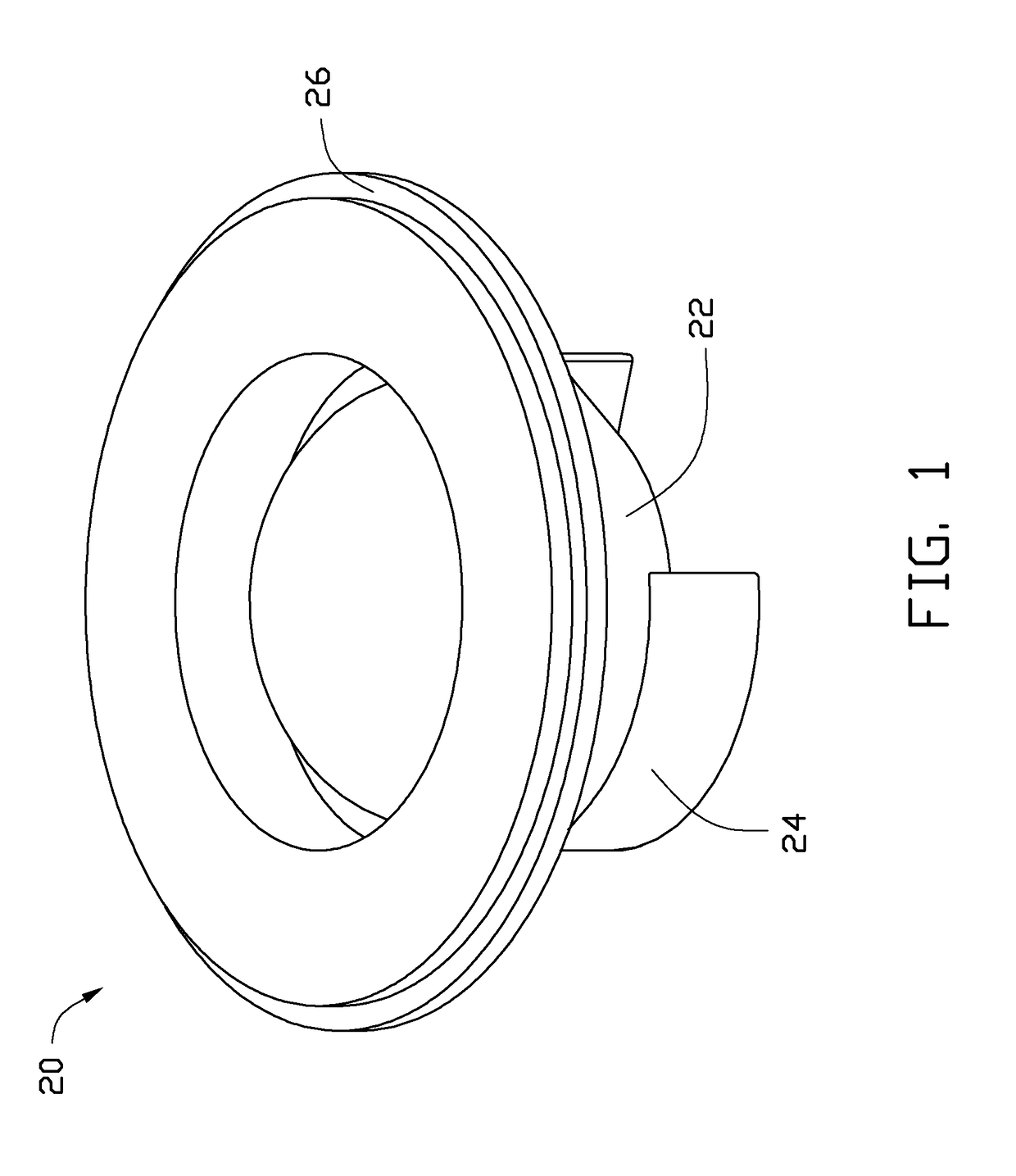
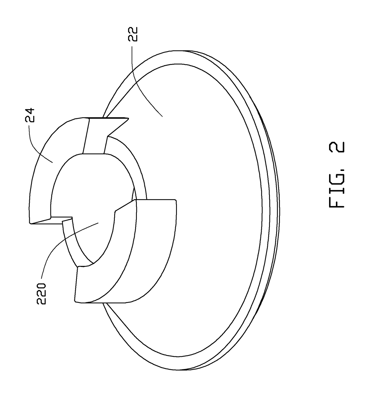
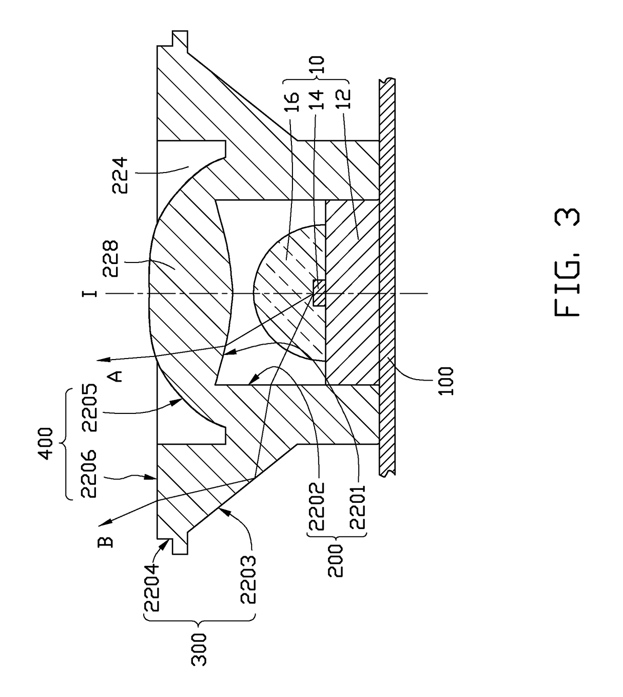
[0012]Referring to FIGS. 1-3, an LED unit of the present disclosure is illustrated. The LED unit comprises an LED 10 and a lens 20 mounted on the LED 10. The LED 10 comprises a heat-conducting base 12, an LED die 14 mounted on a top of the base 12, and an encapsulant 16 covering the LED die 14 and fixed on the top of the base 12. The base 12 of the LED 10 is soldered on a printed circuit board 100 to conduct heat generated by the LED die 14 to the printed circuit board 100. In addition, the LED die 14 is electrically connected with the printed circuit board 100 via the base 12. The LED die 14 may be an InGaN chip, an InGaAs chip, a GaP chip or other suitable chips which could generate visible light with a desirable color. The encapsulant 16 is made of epoxy, silicon, glass or other transparent materials which have good light-permeable and water-proof capabilities. Phosphor may be doped within the encapsulant 16 to adjust the color of the light emitted from the LED die 14. The encaps...


PUM


Abstract

An LED unit includes an LED and a lens mounted on the LED. The lens includes a light-incident face adjacent to the LED, a light-emergent face remote from the LED, and a light-reflecting face between the light-incident face and the light-emergent face. The light-incident face includes a first light-incident face facing the LED, and the light-emergent face includes a first light-emergent face located opposite to the first light-incident face. The first light-incident face is a continuously curved face which has a curvature, along a bottom-to-top direction of the lens, firstly decreasing gradually to a first value; then increasing gradually to a second value; then decreasing gradually again to a third value; and then increasing gradually again. The light-emergent face has a first light-emergent face located above the first light-incident face and having a varied curvature.

Description

BACKGROUND[0001]1. Technical Field[0002]The present disclosure relates to a light emitting diode (LED) unit and, more particularly, to an LED unit having a lens which can produce an effectively converged light beam.[0003]2. Description of Related Art[0004]LEDs, available since the early 1960's and because of their high light-emitting efficiency, have been increasingly used in a variety of occasions, such as residential, traffic, commercial, and industrial occasions. Conventionally, light directly output from the LED does not have a desirable pattern; therefore, a light-adjusting element, such as a lens, is used with the LED to modulate the light pattern thereof. However, a typical lens generally has a limited light-converging capability; that is, the light passing through the lens cannot be effectively converged to have a small light-emergent angle. Thus, the light pattern output from the lens may have a yellow annulus or shining annulus appearing at a periphery thereof, adversely a...

Claims


Application Information

Patent Timeline
Patent Type & Authority Patents(United States)
IPC IPC(8): H01L33/00
CPCF21V5/04F21V7/0091G02B19/0028G02B19/0061F21Y2101/02F21Y2115/10
Inventor CHEN, CHIN-CHUNGSONG, SHI-YU
Owner FU ZHUN PRECISION IND SHENZHEN
Why Eureka
Try Eureka