Secondary lens, solar cell mounting body, light gathering solar energy unit, light gathering solar energy device, and light gathering solar energy module

A solar cell and secondary lens technology, applied in photovoltaic modules, photovoltaic power generation, lenses, etc., can solve the problems of solar cell unit 403 output current reduction, excessive manpower and material resources, etc., to suppress the reduction of fill factor) and alleviate excessive concentration , to prevent the effect of excessive concentration

Inactive Publication Date: 2014-12-10
SHARP KK
View PDF2 Cites 13 Cited by
  • Summary
  • Abstract
  • Description
  • Claims
  • Application Information

AI Technical Summary

Problems solved by technology

Therefore, a holding member for holding the secondary glass 409 is required, and excessive manpower and material resources are required at the time of manufacture, and there are many problems in terms of cost.
[0019] Moreover, due to the transmittance of the secondary glass 409, the loss during total reflection, the light loss in the gap between the outgoing surface and the solar cell 403, etc., there is also a problem that the output current of the solar cell 403 decreases.

Method used


Image

  • Secondary lens, solar cell mounting body, light gathering solar energy unit, light gathering solar energy device, and light gathering solar energy module
  • Secondary lens, solar cell mounting body, light gathering solar energy unit, light gathering solar energy device, and light gathering solar energy module
  • Secondary lens, solar cell mounting body, light gathering solar energy unit, light gathering solar energy device, and light gathering solar energy module

Examples


no. 1 approach 〉

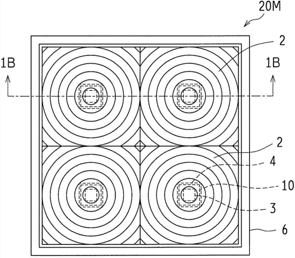
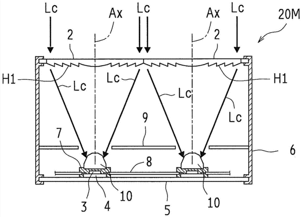
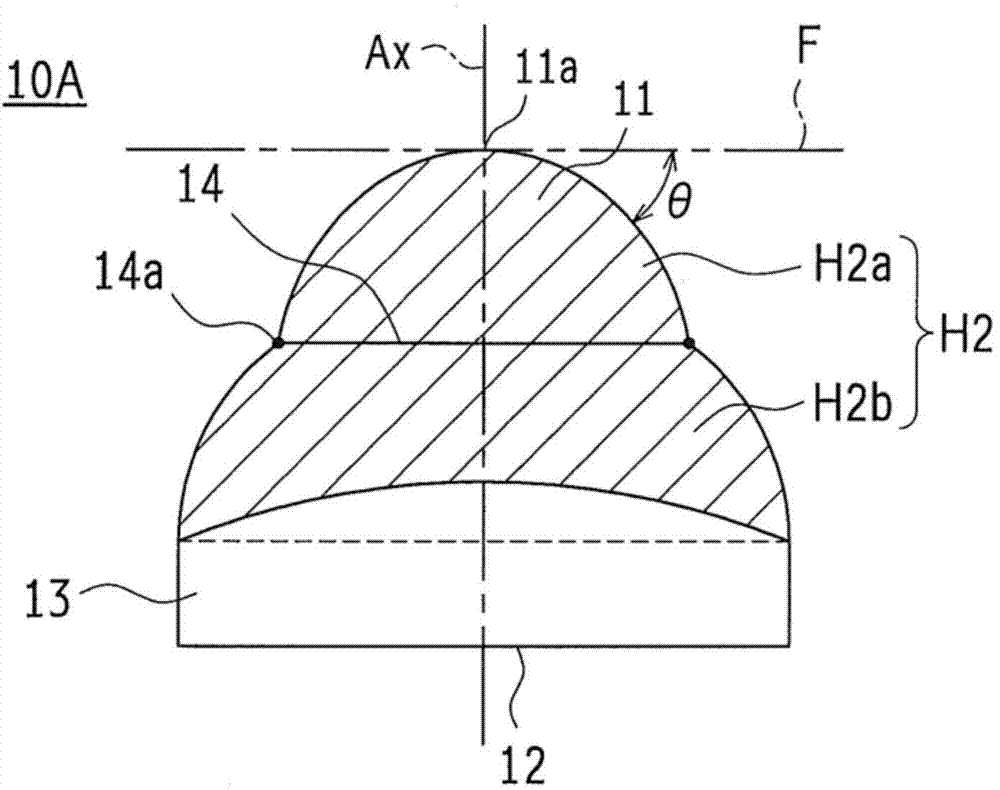
[0156] Figure 1A and Figure 1B It is a schematic diagram illustrating the structure of the concentrating solar power generation module of the present invention, Figure 1A is a plan view viewed from the incident surface of sunlight Lc, Figure 1B yes Figure 1A Sectional drawing of line 1B-1B. and, Figure 2A and Figure 2B Showing the shape of the secondary lens of the first embodiment, Figure 2A for the side view, Figure 2B is a stereogram. in, Figure 2A The oblique lines in indicate the area of ​​the optical refraction surface of the incident part described later.

[0157] The concentrating solar power generation module 20M is a concentrating solar power generation unit in which a concentrating lens 2 which is a primary optical system, a secondary lens 10A which is a secondary optical system according to the first embodiment, and a solar cell 3 are arranged as a set. (hereinafter also simply referred to as cells) are arranged in multiple groups, and in order ...

no. 2 approach 〉

[0199]Next, a second embodiment of the secondary lens will be described.

[0200] Figure 7A to Figure 7D Showing the shape of the secondary lens 10B of the second embodiment, Figure 7A is a stereogram, Figure 7B is a top view, Figure 7C From Figure 7A The side view viewed in the direction of the arrow X1, Figure 7D From Figure 7A A side view viewed in the direction of the arrow X2.

[0201] The difference between the secondary lens 10B of the second embodiment and the secondary lens 10A of the first embodiment is that in the secondary lens 10B of the second embodiment, four positions around the second optical refraction surface H2b are further formed. Corner 16. Therefore, in the secondary lens 10B of the second embodiment, the cross-sectional shape of the second optical refraction surface H2b of the secondary lens 10B in the direction perpendicular to the optical axis is the same as that of the optical refraction surface H1 of the condenser lens 2 in the directi...

no. 3 approach 〉

[0207] refer to Figure 9A to Figure 14B Next, the secondary lens 100 , the concentrating solar power generation device 30 , the concentrating solar power generation module 30M, and the solar cell mounting body 1 of the present embodiment will be described.

[0208] Figure 9A It is a top view showing the concentrating solar power generation device 30 and the concentrating solar power generation module 30M according to the third embodiment of the present invention as viewed from the concentrating lens 2 side.

[0209] Figure 9B so in Figure 9A The cross-sectional state of the arrow 9B-9B indicates Figure 9A A cross-sectional view of the concentrated solar power generation device 30 and the concentrated solar power generation module 30M shown. In addition, in consideration of the convenience of viewing the drawings, shading representing cross-sections is partially added.

[0210] The concentrating solar power generation device 30 has a concentrating lens 2 , which is a ...


PUM


Abstract

Provided is a secondary lens (10A), comprising a first face (11) whereby a gathered light beam from a light gathering lens enters, and a second face (12) which emits the gathered light beam from the light gathering lens toward a solar cell, said secondary lens (10A) guiding entry light to the solar cell by an optical refraction face (H2) which is disposed in the first face (11). A cross-section area of a direction which is perpendicular to an optical axis (Ax) of the gathered light beam of the first face (11) monotonically increases approaching the solar cell side from the light gathering lens side, and there is at least one inflection point (14a) whereat an oblique angle (theta) with respect to the plane of the direction which is perpendicular to the optical axis of the first face (11) declines approaching the solar cell side from the light gathering lens side.

Description

technical field [0001] The present invention relates to a secondary lens used in a concentrating solar power generation module to irradiate solar battery cells with light collected by a concentrating lens, a solar battery mounting body mounted with the secondary lens, and a concentrating solar power generation module using the solar cell mounting body. A solar power generation unit, a concentrated solar power generation device, and a concentrated solar power generation module using the concentrated solar power generation device. Background technique [0002] A solar power generation device that converts solar energy into electricity has been put into practical use. In order to reduce costs, further improve photoelectric conversion efficiency (power generation efficiency), and obtain high power, concentrating solar energy has been proposed that irradiates sunlight collected by a condenser lens to a solar battery unit that is smaller than the condenser lens, thereby extracting...

Claims


Application Information

Patent Timeline
Patent Type & Authority Applications(China)
IPC IPC(8): H02S40/22G02B3/10
CPCY02E10/52H01L31/0543H01L31/048H01L31/02168H01L31/02325
Inventor 植田浩介
Owner SHARP KK
Why Eureka
Try Eureka