Flow guiding device of fluid container and fluid container with flow guiding device

A technology of a diversion device and a fluid container, which is applied to the discharge device and other directions, can solve the problems of liquid leakage, complicated manufacturing process, inconvenient use, etc., and achieves the effect of simple structure, convenient use, and not easy liquid leakage.

Inactive Publication Date: 2012-01-18
钟锐强
View PDF7 Cites 2 Cited by
  • Summary
  • Abstract
  • Description
  • Claims
  • Application Information

AI Technical Summary

Problems solved by technology

These devices need to use some valves and switches to operate and control. The manufacturing process is complicated and it is easy to cause liquid leakage, which causes inconvenience in use.

Method used


Image

  • Flow guiding device of fluid container and fluid container with flow guiding device
  • Flow guiding device of fluid container and fluid container with flow guiding device
  • Flow guiding device of fluid container and fluid container with flow guiding device

Examples


Embodiment 1

[0047] Embodiment 1 (fluid container deflector)

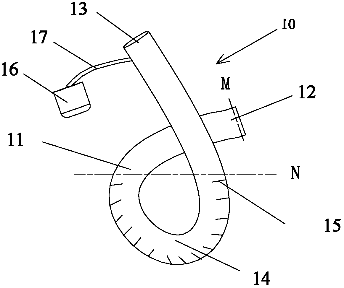
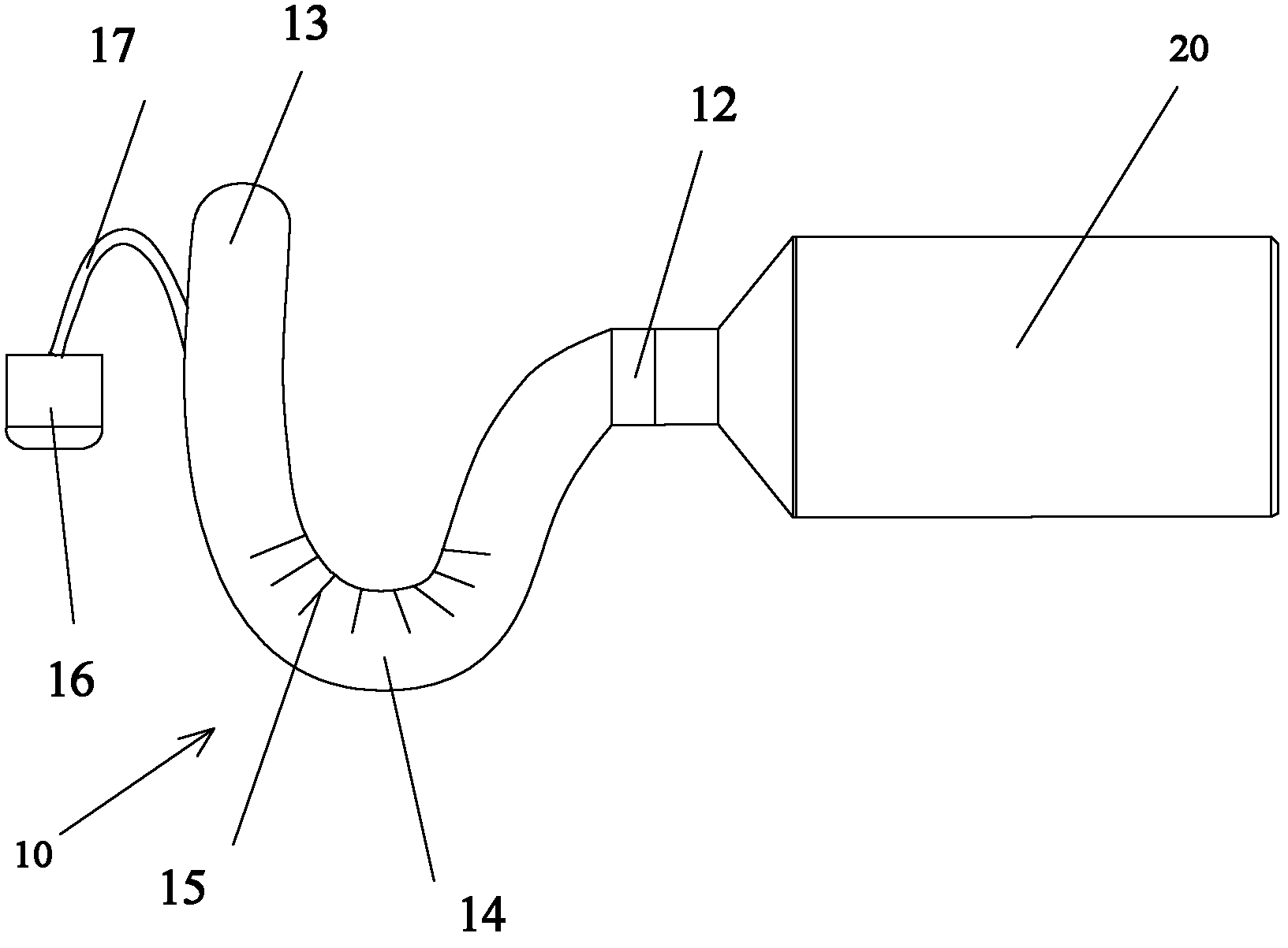
[0048] As shown in Figures 2 and 3, the fluid container diversion device 10 of the present invention is connected to the fluid container 20 at its diversion inlet 12, the fluid container 20 can be a common bottle, and the diversion device 10 is connected at its diversion outlet. 13 places can be externally connected to the fluid receiving container.

[0049] The main body 11 of the flow guiding device 10 is a pipe section made of transparent material with a U-shaped bending part. The "U"-shaped bending part is a spatially twisted U-shape, so the flow channels formed by it are not in the same plane. The diversion body 11 and the diverted fluid container 20 can independently store fluid at the same time. The connection between the body and the fluid container can also be regarded as the initial state as When the shape is connected, the dumping state is shape connected.

[0050] The lumen of the pipe section is the flow ch...

Embodiment 2

[0055] Embodiment 2 (fluid container flow guiding device)

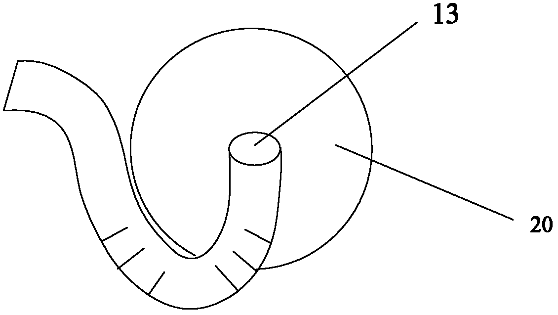
[0056] Such as figure 1 , Figure 5A , Figure 5B and Figure 6 As shown, the difference from the above-mentioned embodiment 1 is that the pipe section of the diversion device 10, its diversion inlet 12, the curved part (temporary storage part 14) and the diversion outlet 13 are in the shape of "∝" in which the space is staggered. , and connected to the fluid container 20. In this embodiment, the fluid is as close as possible to the diverted container during the diversion process, and the torque is relatively reasonable when the diverted container is operated by hand, which is relatively labor-saving.

[0057] Under the condition that the fluid medium in the container 20 no longer flows out of the diversion outlet 13 from the temporary storage part 14 , the container 20 can be rotated so that the diversion flow 12 is gradually lower than the fluid medium volume level in the temporary storage part 14 .

[0058] ...

Embodiment 3

[0064] Embodiment 3 (fluid container with flow guiding device)

[0065] see Figure 8 As shown, the fluid container 30 of the present invention can be a cup body or a jug body, and the inner chamber of the container is provided with a flow guide device (the flow guide device of embodiment 1 or 2, which can also be provided with the inside or outer wall of the container), and the flow guide device The vicinity of the body is a centripetal arc or curved surface, the diversion inlet 31 is formed on the side wall of the cup or pot, the diversion outlet 32 ​​can be separated or not, and there is a certain distance between the outlet and the inlet; The tube section of the device body may be attached to the outer sidewall of the fluid container 30 and may be integrally formed with the outer sidewall of the fluid container 30 . A U-shaped temporary storage part 33 is arranged in the inner cavity of the container. The embodiment of the cup or pot structure can also achieve the purp...


PUM


Abstract

The invention discloses an auxiliary flow guiding device for fluid which comprises a container with a flow channel, a flow guiding inlet and a flow guiding outlet. Through arranging a flow guiding direction of the flow channel, the fluid is poured into from the flow guiding inlet when being used; after the guided gross is observed, a horizontal state is restored; the fluid is stored into the container and then is poured outside from the flow guiding outlet; and the double pouring are guided along the different horizontal directions so that the guiding-into and the guiding-out of the fluid are not mutually interfered. The quantity can be observed when the fluid is stored into an auxiliary guiding-out container; or the fluid is cooled to guide outside. The guiding-out device is simply structured so that the quantity to be required to be guided outside can be clearly observed; therefore, the guiding-out device is convenient to use.

Description

technical field [0001] The invention relates to a flow guide device for a fluid container, in particular to a device capable of quantitatively guiding fluid medium condiments such as edible oil, salt, soy sauce and the like. Background technique [0002] People often need to take out some fluid media in small doses from the container in daily life, such as taking out some liquid seasonings such as edible oil, soy sauce, salt, sugar when cooking. Due to the large volume and heavy weight of the containers for storing these liquid seasonings, it is easy to scatter and difficult to properly guide according to the amount when leading, which brings inconvenience to people's lives. [0003] At present, there are some liquid guide devices that use the opening and closing of the guide nozzle or the diameter of the guide nozzle to control the flow rate. For example, in the Chinese invention patent application number 200520083221.6, an oil guide pipe is connected to the top of the oil ...

Claims


Application Information

Patent Timeline
Patent Type & Authority Applications(China)
IPC IPC(8): B65D25/52
Inventor 钟锐强
Owner 钟锐强
Why Eureka
Try Eureka