Automatic calibrating device and method for temperature measuring channel of acquisition device in weather station

An automatic weather station, temperature measurement technology, used in measurement devices, thermometer testing/calibration, thermometers, etc., can solve the problems of temperature drift, coordination problems, insufficient precision resistance, etc., to eliminate temperature drift and relay contact. The influence of resistance, the effect of meeting the verification requirements and reducing the deviation

Inactive Publication Date: 2013-01-02
NANJING UNIV OF INFORMATION SCI & TECH
View PDF5 Cites 0 Cited by
  • Summary
  • Abstract
  • Description
  • Claims
  • Application Information

AI Technical Summary

Problems solved by technology

The disadvantage of this method is: the accuracy of precision resistors that can be selected at present can only reach ±100mΩ, and there is a phenomenon of temperature drift, while the meteorological industry requires resistance accuracy of ±30mΩ
A large number of tests have shown that there are problems with the cooperation of active resistors with most of the collectors that are being used in business, and normal verification cannot be achieved
[0006] Therefore, the current predicament in the temperature verification of the collector is: the accuracy of the precision resistor is not enough when choosing the precision resistor solution, and the active resistor cannot cooperate with most collectors to achieve the verification

Method used


Image

  • Automatic calibrating device and method for temperature measuring channel of acquisition device in weather station

Examples


Embodiment Construction

[0025] Below in conjunction with accompanying drawing, the technical scheme of invention is described in detail:

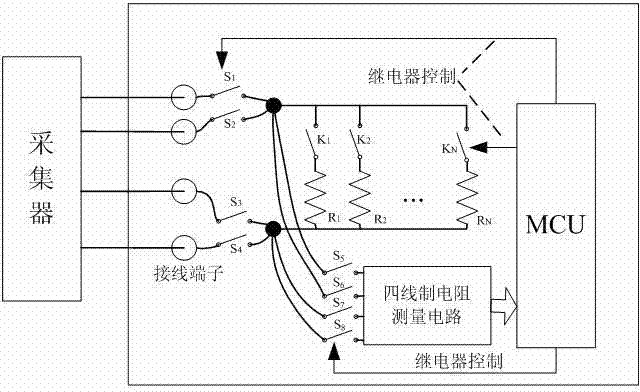
[0026] A verification device for the temperature measurement channel of an automatic weather station collector, comprising a collector, first to fourth access relays, a resistance circuit, a four-wire resistance measurement circuit, fifth to eighth access relays, and an MCU controller;

[0027] Wherein, the four connection terminals of the collector are respectively connected to the input ends of the first to fourth access relays;

[0028] The input terminals of the resistance circuit are respectively connected with the output terminals of the first and second access relays, and the input terminals of the fifth and sixth access relays;

[0029] The output terminals of the resistance circuit are respectively connected with the output terminals of the third and fourth access relays, and the input terminals of the seventh and eighth access relays;

[0030] The outpu...


PUM

PropertyMeasurementUnit
electrical resistanceaaaaaaaaaa

Abstract

The invention relates to an automatic calibrating device and method for a temperature measuring channel of an acquisition device in a weather station, belonging to the technical field of detection of instruments and meters. The calibrating device disclosed by the invention is combined with a resistance circuit and a four-wire system resistance circuit. The method disclosed by the invention comprises the following steps of: controlling the on / off of the acquisition device and the four-wire system resistance circuit accessed to a relay according to the resistance set by a user and realizing theswitch between the four-wire system resistance circuit and an acquisition device measuring circuit through a controller; displaying the measuring result of the four-wire system resistance circuit, converting the measured resistance into a temperature value and displaying the temperature value through the controller; and finally, controlling the relay to abut the acquisition device with the resistance circuit, realizing the calibrating measurement of the acquisition device and comparing a measuring value of the acquisition device with a display value output by the controller through the controller to obtain a calibrating error. According to the device and the method disclosed by the invention, the output resistance is accurately measured in a real time; the deviation between an actual output value and a nominal value of the resistance is greatly reduced; the influence from the temperature drift of the resistance and the contact between the relay and the resistance is eliminated; and the calibrating requirement of the acquisition device is completely met.

Description

technical field [0001] The invention relates to a verification device and a verification method for a temperature measurement channel of an automatic weather station collector, belonging to the technical field of instrumentation and detection. Background technique [0002] Currently distributed all over the country, there are tens of thousands of automatic weather stations in mountains, islands, deserts and frontiers, which are used to automatically collect meteorological elements in various places in real time, among which temperature is one of the most important meteorological elements that need to be measured. The automatic weather station is composed of a sensor and a collector. The temperature measurement sensor usually uses a platinum resistor (PT100). Therefore, the accurate measurement of the resistance value of the platinum resistance is a key factor in the accurate measurement of temperature. However, as the environment and time of the collector change, the resist...

Claims


Application Information

Patent Timeline
Patent Type & Authority Patents(China)
IPC IPC(8): G01K15/00
Inventor 邹应全
Owner NANJING UNIV OF INFORMATION SCI & TECH
Why Eureka
Try Eureka