Video camera imaging objective lens and airborne photoelectric helmet aiming system thereof

An imaging objective lens and camera technology, which is applied in the field of objective lens, can solve the problems of limited camera installation position, narrow space, general camera cannot meet the precise positioning and head movement range, and achieve the effect of improving imaging quality

Inactive Publication Date: 2012-01-18
中航华东光电有限公司
View PDF1 Cites 21 Cited by
  • Summary
  • Abstract
  • Description
  • Claims
  • Application Information

AI Technical Summary

Problems solved by technology

However, due to the narrow space in the aircraft cockpit, the installation position of the camera is limited, so that the general-purpose camera cannot meet the requirements of precise positioning and the range of head movement.
[0004] The existing camera (CCD) imaging objective lens on the market may meet the requirements of the helmet sighting system in terms of size, field of view or resolution, but it is difficult to meet the requirements of the helmet sighting system in the above three aspects at the same time

Method used


Image

  • Video camera imaging objective lens and airborne photoelectric helmet aiming system thereof
  • Video camera imaging objective lens and airborne photoelectric helmet aiming system thereof
  • Video camera imaging objective lens and airborne photoelectric helmet aiming system thereof

Examples


Embodiment Construction

[0041] In order to make the object, technical solution and advantages of the present invention clearer, the present invention will be further described in detail below in conjunction with the accompanying drawings and embodiments. It should be understood that the specific embodiments described here are only used to explain the present invention, not to limit the present invention.

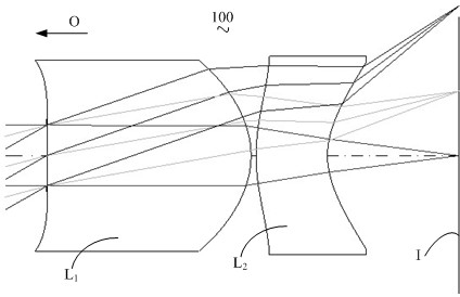
[0042] see figure 1 , which is a schematic diagram of the structure of the camera imaging objective lens 100 provided in the preferred embodiment of the present invention. The camera imaging objective lens 100 is applied to the airborne photoelectric helmet aiming system (not shown in the figure) to solve the problem of using the existing camera in the helmet aiming system. The technical problems that exist at the time, such as solving spherical aberration and coma, eliminating monochromatic aberration and minor advanced aberration, etc.

[0043] Camera imaging objective lens 100 sequentially incl...


PUM


Abstract

The invention relates to a video camera imaging objective lens. The video camera imaging objective lens is applied in an airborne photoelectric helmet aiming system. From an object side to an imaging surface, the video camera imaging objective lens comprises a diaphragm, a first lens and a crescent-shaped second lens in turn, wherein the first lens has a rear focus of which focal power on one side of the imaging surface is positive; the crescent-shaped second lens has a concave surface which has very high curvature, and the focal power facing one side of the imaging surface is negative; at least one surface of both the first lens and the second lens is a non-spherical surface and is in accordance with conditional formula: 1.3<f/f1<2.1 and -1.9<f/f2<-0.5, wherein f is the focal length of the video camera imaging objective lens; f1 is the focal length of the first lens; and f2 is the focal length of the second lens. The video camera imaging objective lens can correct a spherical aberration and a coma of the airborne photoelectric helmet aiming system. The invention also relates to the airborne photoelectric helmet aiming system with the video camera imaging objective lens.

Description

technical field [0001] The invention relates to an objective lens, in particular to a camera imaging objective lens and an airborne photoelectric helmet aiming system with the camera imaging objective lens. Background technique [0002] With the continuous development of fighter planes and airborne weapons, and the continuous improvement of ergonomic requirements, it is of great significance to study the integrated display / aiming system technology of airborne helmets in the field of aviation display and fire control. The newly equipped F-35 Joint Strike Fighter in the United States uses a helmet-mounted integrated display / targeting system to replace the head-up display system, realizing the combat effect of "finding the enemy first and firing first" and the ability to launch large off-axis missiles. [0003] The integrated display / aiming system of the airborne helmet adopts the photoelectric helmet-aiming method based on video image processing. This method installs a set of...

Claims


Application Information

Patent Timeline
Patent Type & Authority Applications(China)
IPC IPC(8): G02B13/18G02B27/01
Inventor 杨新军董戴李刚闫记香
Owner 中航华东光电有限公司
Why Eureka
Try Eureka