Concrete mixer truck

A technology for a concrete mixer truck and a mixing drum is applied in the directions of concrete transportation, vehicle components, and substructures, which can solve the problems of inconsistency in structure and affect the installation space of other components, and achieve the effect of low cost.

Active Publication Date: 2012-01-25
SANY AUTOMOBILE MFG CO LTD
View PDF4 Cites 14 Cited by
  • Summary
  • Abstract
  • Description
  • Claims
  • Application Information

AI Technical Summary

Problems solved by technology

The above structure is not simple, and the background se

Method used


Image

  • Concrete mixer truck
  • Concrete mixer truck
  • Concrete mixer truck

Examples


Embodiment Construction

[0019] The following will clearly and completely describe the technical solutions in the embodiments of the present invention with reference to the accompanying drawings in the embodiments of the present invention. Obviously, the described embodiments are only some, not all, embodiments of the present invention. Based on the embodiments of the present invention, all other embodiments obtained by persons of ordinary skill in the art without creative efforts fall within the protection scope of the present invention.

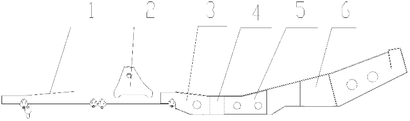
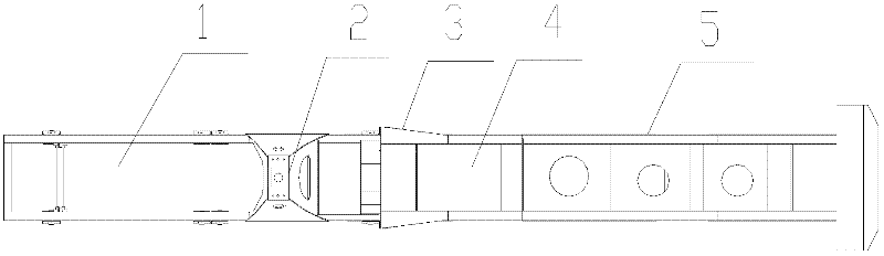
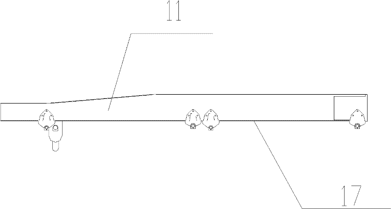
[0020] Consistent with the prior art, the concrete mixer truck of the present invention includes a cab, a main frame, a mixing drum, a front assembly and a supporting wheel assembly, the main frame includes two longitudinal beams, and the cab is fixed on the side of the longitudinal beams. One end; the difference lies in the improvement of the structure of the main frame, which will be explained below mainly based on the embodiments of the main frame. Such as Pict...


PUM


Abstract

The invention provides a concrete mixer truck. The concrete mixer truck comprises a driving cab, a main truck frame, a mixing drum, a foreground assembly and a supporting wheel assembly, wherein the main truck frame comprises two longitudinal beams; the driving cab is fixedly arranged at one end of a longitudinal beam; one end, far away from the driving cab, of the longitudinal beam is inclined upwards relative to the horizontal plane; and the supporting wheel assembly is directly arranged at one end, far away from the driving cab, of the longitudinal beam. In the concrete mixer truck, one end, far away from the driving cab, of the longitudinal beam is provided with the supporting wheel assembly directly by upwards inclination, so background materials are saved, and arrangement space for other accessories is remained and the cost is low.

Description

technical field [0001] The invention relates to the field of engineering machinery, in particular to a concrete mixer truck. Background technique [0002] Concrete mixer truck is a special heavy-duty vehicle for concrete transportation. Its transportation quality is large, the operating environment is a construction site, and the road environment is very harsh. In addition, the long-term operation of the mixer truck puts forward strict requirements on the reliability of the frame and upper body. , Long-term use of the frame will produce deformation phenomena such as sinking at both ends and bulging in the middle, and twisting of the beam. [0003] At present, most concrete mixer trucks are equipped with a sub-frame on the main frame of the chassis, that is, the front and back of the mixing drum are respectively installed on the sub-frame, and then the sub-frame is connected to the chassis through "U"-shaped connecting bolts or other methods. On the main frame, the fixing of...

Claims


Application Information

Patent Timeline
IPC IPC(8): B60P3/16B62D21/18
Inventor 田飞云张博廖国防
Owner SANY AUTOMOBILE MFG CO LTD
Why Eureka
Try Eureka