[0013] The accompanying drawings disclose, without limitation, structural schematic diagrams of preferred embodiments involved in the present invention. The technical solutions of the present invention will be described in detail below in conjunction with the accompanying drawings.
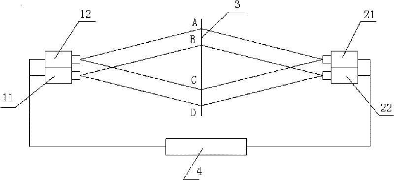
[0014] like figure 1 As shown, in the high-frequency acquisition method of PIV images described in the present invention, at first, two groups of camera arrays are arranged symmetrically, and each group of camera arrays includes at least two cameras; Shoot the tracer particles in the flow field in the field of view, and input the images taken by each camera into the computer; use autocorrelation technology to process the particle images taken by each camera, and obtain the flow field vector data in the corresponding field of view of each camera, and at the same time , the coordinate transformation relationship between the image information captured by each camera and the light plane 3 is established through calibration, so as to convert the corresponding flow field vector data of the images captured by each camera into the coordinate system of the light plane 3, so as to obtain Each camera captures flow velocity data at different moments in the overlapped portion of the field of view. The camera array is composed of a group of cameras whose axial normals are parallel to each other, and the distances between the cameras forming the camera array and the flow field are consistent, and the axial normals of each camera are perpendicular to the sheet light surface. Each camera of each camera array is connected to the output end of the same reciprocating linear moving device, and the moving direction of the reciprocating linear moving device is perpendicular to the sheet light plane 3 .
[0015] Adopt technical scheme of the present invention to carry out the process of PIV experiment as follows:
[0016] like figure 2 As shown, the synchronizer at t 1 Time period controls the first camera 11 to perform double exposure, the time interval of double exposure is △t, after the first camera 11 completes the double exposure to collect images, after △T time, the synchronizer at t 2 The time period controls the second camera 12 to perform double exposure, and the double exposure time interval is △t. After the second camera 12 completes the double exposure acquisition image, after △T time, the third camera 21 is controlled, and each camera is sequentially controlled to perform double exposure. Expose and collect images, and the camera array completes time-series image collection.
[0017] to t 1 The double-exposure images collected by the first camera 11 during the time period are subjected to autocorrelation calculations to obtain t 1 The average velocity of the time period V 11 , the control △t time is short enough, that is, t 1 For a short period of time, V 11 can be regarded as t 1 The moment is the instantaneous flow velocity. In the same way, the instantaneous flow velocity V of the second, third and fourth cameras 22 is obtained 22 , V 23 , V 24. Similarly, the flow velocity over the entire time series can be obtained: V 11 , V 22 , V 23 , V 24 , V 15 , V 26 , V 27 , V 28...
[0018] If the sampling frequency of the camera is f, after the synchronizer is controlled, the sampling frequency of PIV will be 4×f. For example, the frequency of a domestic conventional camera can be 60HZ in the case of a resolution of 1024*768. This kind of camera array layout is adopted Finally, the sampling frequency of PIV can reach 240, which can meet most of the water flow turbulence analysis. The domestic resolution 1024*768 can reach 200HZ cameras. About 1,000 yuan, the price of 4 identical cameras is also far lower than that of high-frequency cameras.
[0019] The 3-coordinate transformation relationship between each camera image and the slice light plane is established through calibration. The coordinates of the origin of the sheet light in the image of the first camera 11 are , the point where the sheet light plane 3 intersects the axis of the flow field is generally defined as the origin of the sheet light plane 3 coordinate system; the actual size of the sheet light plane represented by each pixel of the first camera 11 is , 11 image coordinates for the first camera Convert to coordinates of sheet light plane 3:
[0020] Similarly, the coordinate conversion relationship between the second camera 12 and the light plane 3 can be obtained as follows:
[0021]
[0022] Since the third and fourth cameras 22 and the first and second cameras also have vertical mirror images, the resolution of the cameras is Then the coordinate conversion relationship between the third and fourth cameras 22 and the light plane 3 of the laser sheet is:
[0023]
[0024]
[0025] In the case of ensuring that the technical parameters of each camera are consistent, if the distances between each camera and the light plane 3 are equal, then there is.
[0026] The first camera 11 and the second camera 12 are in the same array, and the axis normals are parallel, so the distance b between the axis normals and the image coordinates of the first camera 11 and the second camera 12 have the following relationship:
[0027]
[0028] Similarly, the image coordinates of the third camera 21 and the fourth camera 22 in the same array have the following relationship:
[0029]
[0030] It can be seen from the arrangement form diagram of the camera array that in the light plane 3, the first camera 11 and the third camera 21 have the same shooting range, the second camera 12 and the fourth camera 22 have the same shooting range, and the overall Seen from above, the overlapping portion of the field of view of each camera is the portion of the light plane 3B-C.
[0031] After transforming the vector data coordinates of each camera into 3-coordinates of the sheet light plane, as long as the coordinates are between B-C, it is the overlapping part of the field of view.
[0032] Acquired time series velocity: V 11 , V 22 , V 23 , V 24 , V 15 , V 26 , V 27 , V 28...
[0033] For sheet light plane 3 coordinates The instantaneous flow rate is: , ,...
[0034] The 3-coordinates of the sheet light plane The average flow rate of is:
[0035]
[0036] t 1 The pulse velocity at time is
[0037] Then t 2 , t 3 , t 4…… The momentary pulsating flow rate is:
[0038]
[0039]
[0040]
[0041]...
[0042] The characteristics of water flow turbulence can be analyzed through the above formula.