Spring clamp element and terminal

A spring clip and component technology, applied in the field of spring clip components, can solve the problems of increasing the structure height, bulkiness, large space, etc., and achieve the effect of reducing the structure size

Active Publication Date: 2015-04-01
WAGO VERW GMBH
View PDF9 Cites 2 Cited by
  • Summary
  • Abstract
  • Description
  • Claims
  • Application Information

AI Technical Summary

Problems solved by technology

Therefore, the connecting clamp equipped with such a tension clamp-spring clamp connection must be designed relatively bulky, which has a negative impact on the overall size
In addition, the operating components occupy a large space above the tension bridge, which in turn increases the construction height

Method used


Image

  • Spring clamp element and terminal
  • Spring clamp element and terminal
  • Spring clamp element and terminal

Examples


Embodiment Construction

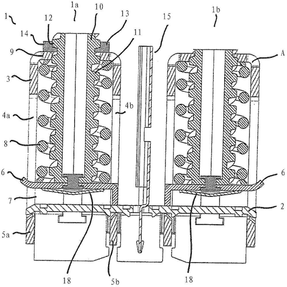
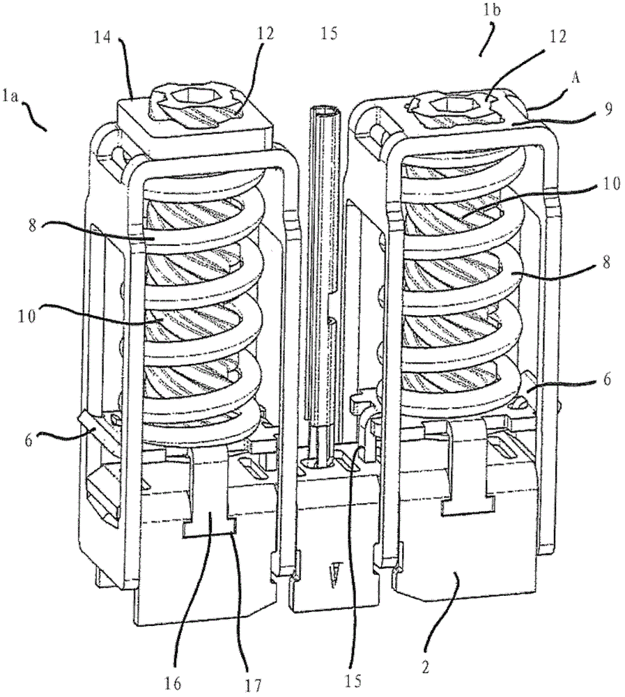
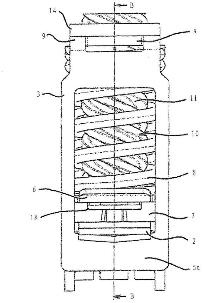
[0042] Depend on figure 1 A first embodiment of the spring clip element 1 can be seen. In the exemplary embodiment shown, two spring clip elements 1 a , 1 b are realized on a common busbar part 2 .

[0043] The spring clip elements 1a, 1b each utilize a section of the busbar part 2 in which the tensioning bar 3 is displaceably mounted. For this purpose, the tensioning strip 3 has, for example, on its opposite side walls openings 4 a , 4 b through which the busbar 2 passes. The openings 4 a , 4 b are each delimited by a clamping edge 5 a , 5 b arranged below the busbar 2 .

[0044] In this exemplary embodiment, the busbar part 2 has a tunnel plate 6 which, starting from the busbar part 2 , is bent into a section extending parallel to the busbar part 2 , so that a tunnel between the busbar part 2 and the tunnel plate 6 is formed. The connecting cavity 7 between the inner walls. Arranged above the tunnel plate 6 is a helical spring 8 in the form of a helical compression sprin...


PUM


Abstract

The spring clamping element (1) has a current rail piece (2) and a pull bow (3) which is movably supported at the current rail piece relative to the current rail piece, where the pull bow has a clamping edge (5a,5b) for clamping an electrical conductor between the clamping edge and current rail piece. An actuating cylinder (10) is rotated with a screw thread and is supported at the pull bow or at current rail piece in extension direction of the actuating cylinder. An independent claim is also included for a series terminal with an insulating housing.

Description

technical field [0001] The invention relates to a spring clip element having: [0002] - a contact rail piece, [0003] - a tension clamping plate (Zugbügel) or a bow clamp, which is movably supported on the conductor rail part relative to the conductor rail part and has at least one clamping edge for clamping the conductor rail part from below, and the clamping edge is used for clamping electrical conductors located between the clamping edge and the contact rail piece, and [0004] - A helical spring operatively connected to the contact rail piece and the tension clamping plate and exerting a spring force between the tensioning clamping plate and the contact rail piece. [0005] Furthermore, the invention relates to a terminal box with an insulating material housing and at least one spring clip element accommodated in the insulating material housing. Background technique [0006] This tension clamp - spring connector is especially suitable for high current applications. ...

Claims


Application Information

Patent Timeline
Patent Type & Authority Patents(China)
IPC IPC(8): H01R4/48H01R9/00
CPCH01R9/26H01R4/4872
Inventor 斯蒂芬.加索尔詹.斯图斯洛夫弗兰克.哈特曼
Owner WAGO VERW GMBH
Why Eureka
Try Eureka