
Lower vehicle-body structure of vehicle

一种车身、车辆的技术,应用在下部结构、车辆部件、运输和包装等方向,能够解决妨碍臂部件和副车架、无法确保冲击负荷溃缩空间等问题,达到提高安装刚性、确保溃缩空间、降低负载噪声的效果

Inactive Publication Date: 2012-02-08
MAZDA MOTOR CORP
View PDF7 Cites 24 Cited by
  • Summary
  • Abstract
  • Description
  • Claims
  • Application Information

AI Technical Summary

Problems solved by technology

[0009] However, connecting and supporting the rear portion of the arm member to both the subframe and the front side member as described above may prevent the arm member and the subframe from being smoothly disengaged and retreated in the event of a frontal collision, and it is impossible to ensure sufficient Crash space to absorb shock loads

Method used


Image

  • Lower vehicle-body structure of vehicle
  • Lower vehicle-body structure of vehicle
  • Lower vehicle-body structure of vehicle

Examples


Embodiment Construction

[0049] Hereinafter, an embodiment of the present invention will be described with reference to the drawings.

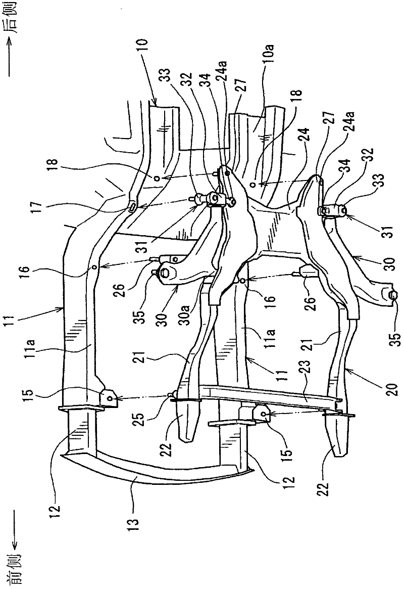
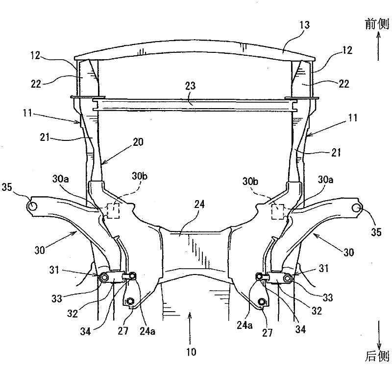
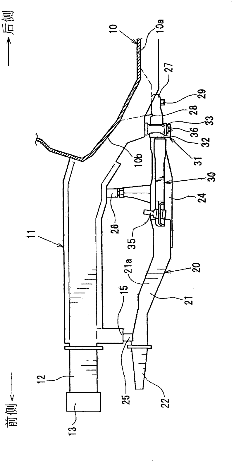
[0050] figure 1 A perspective view showing the underbody structure at the front of the vehicle body when viewed from the bottom, figure 2 Bottom view of the underbody structure showing the front of the vehicle body, image 3 Left side view of the lower body structure showing the front of the body, Figure 4 An explanatory diagram showing the fourth connected portion 17, Figure 5 A perspective view of the rear connecting member 31 viewed from the bottom is shown. in addition, Figure 4 (a) represents the bolt penetration hole 17b in this embodiment, Figure 4 (b) shows a modified example of the bolt penetration hole 17b.

[0051] In addition, in this specification, a front part means the part of a vehicle front side, and a rear part means a part of a vehicle rear side.

[0052] Such as figure 1 , figure 2 and image 3 As shown, the lower vehicle body struc...


PUM


Abstract

In a lower vehicle-body structure of a vehicle, there is provided a rear connecting member (31) swingably supporting a rear portion of a lower arm (30) at a sub frame (20) and a front side frame (11), the rear connecting member (31) comprising a support portion (32) to support the lower arm (30), a fifth connection portion (34) to connect the sub frame (20) and the support portion (32), and a fourth connection portion (33) to connect the front side frame (11) and the support portion (32). Further, there is provided a separation mechanism to separate the fourth connection portion (33) off the front side frame (11) in the vehicle frontal collision. Accordingly, the sub frame and the lower arm are separated off the front side frame by the separation mechanism.

Description

technical field [0001] The present invention relates to an underbody structure of a vehicle in which an arm member constituting a suspension device is connected to a subframe at, for example, a front portion of an automobile body. Background technique [0002] Conventionally, there is an underbody structure of a vehicle in which a crumple space is provided at the front of the vehicle body to absorb the impact load from the front of the vehicle to absorb the impact. More specifically, this underbody structure can be bent along with the front side beams by forming a pair of left and right front side members that are provided at the front of the vehicle body and extend in the front-rear direction into a structure that is easily bent and deformed by an impact load. Deformation to absorb the impact load from the front of the vehicle in a frontal collision. The space (section) in which the impact load is absorbed by such bending deformation of the front side member is called a cr...

Claims


Application Information

Patent Timeline
Patent Type & Authority Applications(China)
IPC IPC(8): B62D21/00B62D21/15
CPCB62D21/155B62D21/11
Inventor 山田健山内一树竹下弘明福岛正信
Owner MAZDA MOTOR CORP
Learn More