Plugged box with distribution automation

A technology of power distribution automation and plug-in box, which is applied in the direction of electrical components, substation/switch layout details, etc., can solve the problems of poor overall rigidity, inability to install the motherboard quickly and conveniently, and inconvenient installation and use, so as to achieve structural transformation and plug-in , Easy replacement and assembly, simple structure and practical effect

Active Publication Date: 2012-02-15
QINGDAO ITECHENE TECH CO LTD
View PDF6 Cites 2 Cited by
  • Summary
  • Abstract
  • Description
  • Claims
  • Application Information

AI Technical Summary

Problems solved by technology

[0002] At present, in the commonly used power distribution automation subracks or communication subracks, the motherboards of many subracks are placed in the middle, and the single board is inserted from the back, or the front and rear are inserted into the single board, and the motherboard is fixed by screws. In the existing structural designs, there are other beams on the front and back of the motherboard, guide rails on the beams, shielding side panels on the left and right, etc., which block the beams and mounting holes for fixing the motherboard. When installing or replacing the motherboard Many parts in the sub-box must be disassembled, so that the motherboard located inside cannot be installed quickly and conveniently; in some existing distribution automation sub-boxes, the rear sub-box is used as a detachable sub-assembly. After the motherboard is installed, the rear sub-box is assembled on the main body of the sub-box. This structure and technical solution occupy a lot of space inside the sub-box, and because the rear sub-box is detachable, the sub-box structure becomes complicated. The overall rigidity is also poor, and the cost is also increased a lot; in conclusion, these existing box insertion devices generally have complex structures, inconvenient installation and use, cumbersome insertion procedures, high manufacturing costs, short service life, low automation and safety. Poor performance and other disadvantages

Method used


Image

  • Plugged box with distribution automation
  • Plugged box with distribution automation
  • Plugged box with distribution automation

Examples


Embodiment

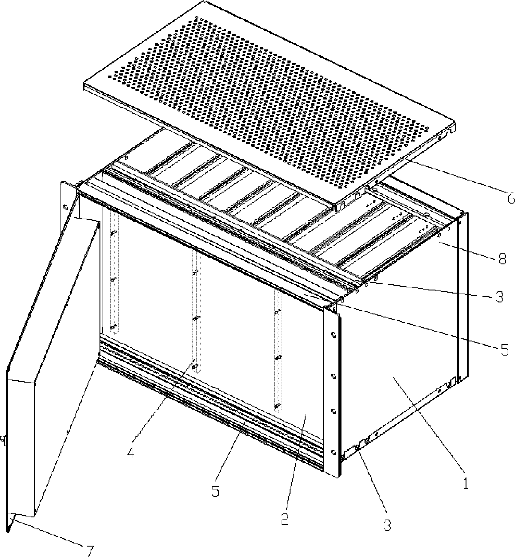
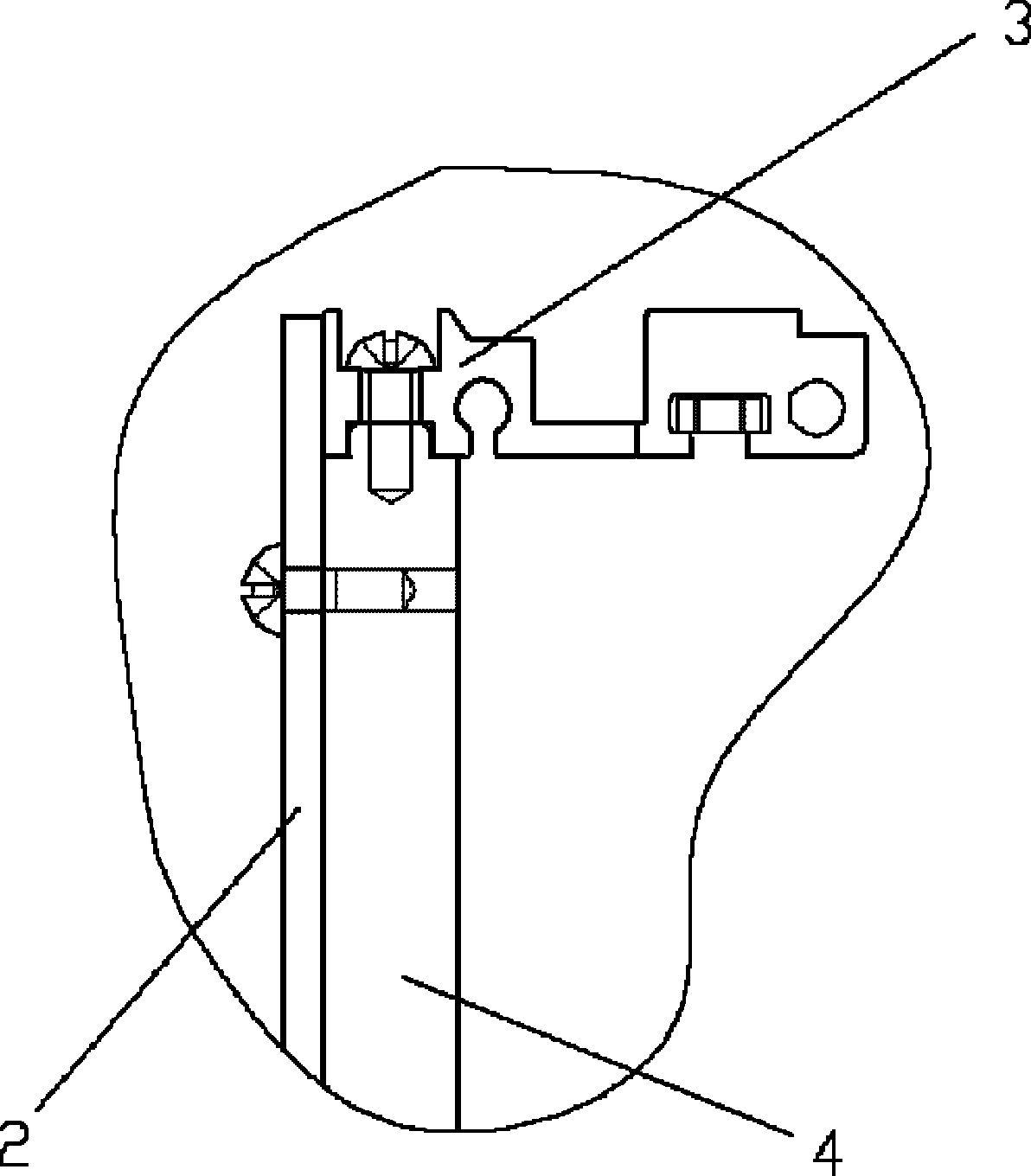
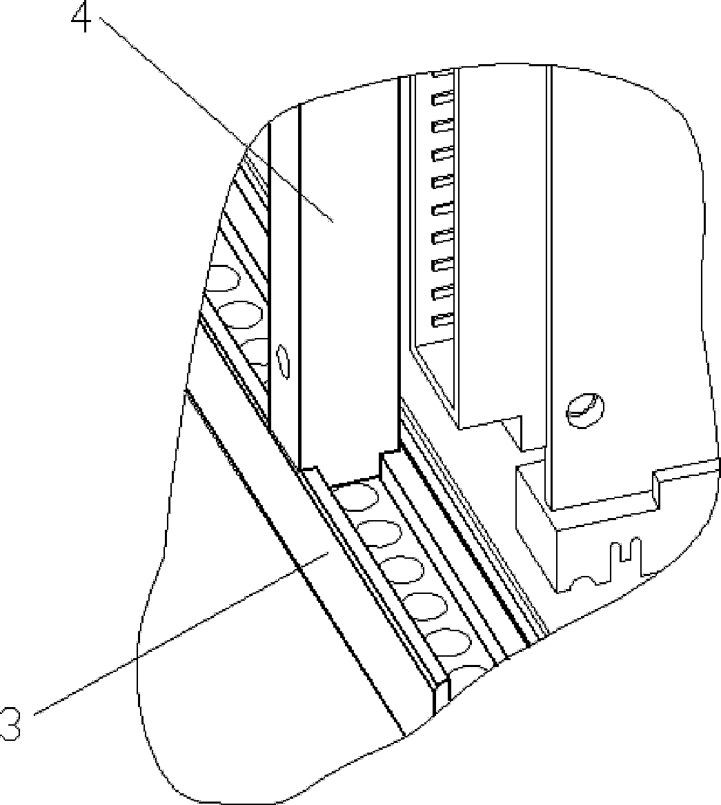
[0011] The main structure of this embodiment includes a box body 1, a motherboard 2 fixed in the box body, a cover plate 6 placed on the top of the box body, a middle beam 3 placed between side panels 8, and a front beam 5, which are connected with the upper and lower sides. The vertical beam 4 between the middle beams 3 is placed on the front panel 7 at the front of the box body 1; there is a certain opening distance between the front beam 5 in the box body and the middle beam 3, which is greater than the front and back depth of the motherboard 2, The opening distance is located under the cover plate 6; the opening distance of the box body 1 is distributed on the top and bottom of the box body; the motherboard 2 enters the box body 1 through the opening, clings to the corresponding vertical beam 4, and is fixed to the vertical beam 4 by screws On the middle crossbeam 3, there is an inverted groove, which is distributed on the upper and lower parts of the middle crossbeam 3, an...


PUM


Abstract

The invention belongs to the field of distribution automation control technical equipment and relates to a plugged box with distribution automation, which is characterized in that: the top part of a box body in a box-shaped structure is provided with a cover plate in a ventilated structure; two side faces of the box body are respectively provided with a side panel in a plug-in structure; the front part of the box body is provided with a fixed front panel, middle cross beams and front cross beams which are distributed vertically are arranged between the two side panels; an opening space is reserved between each middle cross beam and each front cross beam; vertical beams which are sequentially spaced are arranged on the middle cross beams, pass through the upper and lower middle cross beams and are fixedly arranged between the middle cross beams; the middle cross beams and the vertical beams are arranged in a same plane; and a motherboard is arranged on a corresponding structural position of the vertical beams and the middle cross beams. The plugged box with distribution automation has a simple and practical structure, is provided with the mother board which is convenient and easy to replace and assemble, has low cost, strong integral stiffness and wide applied range, and can effectively realize conversion and plug-in of structures of a distribution automation device.

Description

Technical field: [0001] The invention belongs to the field of power distribution automation control technology equipment, and relates to a power distribution automation sub-box, in particular to a device for plugging in various power distribution structural parts in a power distribution device. Background technique: [0002] At present, in the commonly used power distribution automation subracks or communication subracks, the motherboards of many subracks are placed in the middle, and the single board is inserted from the back, or the front and rear are inserted into the single board, and the motherboard is fixed by screws. In the existing structural designs, there are other beams on the front and back of the motherboard, guide rails on the beams, shielding side panels on the left and right, etc., which block the beams and mounting holes for fixing the motherboard. When installing or replacing the motherboard Many parts in the sub-box must be disassembled, so that the mother...

Claims


Application Information

Patent Timeline
Patent Type & Authority Applications(China)
IPC IPC(8): H02B1/46
Inventor 吴金博
Owner QINGDAO ITECHENE TECH CO LTD
Why Eureka
Try Eureka