Totally-enclosed main motor for vehicle

A main motor, fully closed technology, applied in the direction of electric components, electrical components, electromechanical devices, etc., can solve the problem of motor size limitation, and achieve the effect of ensuring cooling performance and reducing length and size

Active Publication Date: 2012-02-15
KK TOSHIBA
View PDF6 Cites 28 Cited by
  • Summary
  • Abstract
  • Description
  • Claims
  • Application Information

AI Technical Summary

Problems solved by technology

i.e. the motor 301 has very strict size constraints

Method used


Image

  • Totally-enclosed main motor for vehicle
  • Totally-enclosed main motor for vehicle
  • Totally-enclosed main motor for vehicle

Examples


Embodiment 1

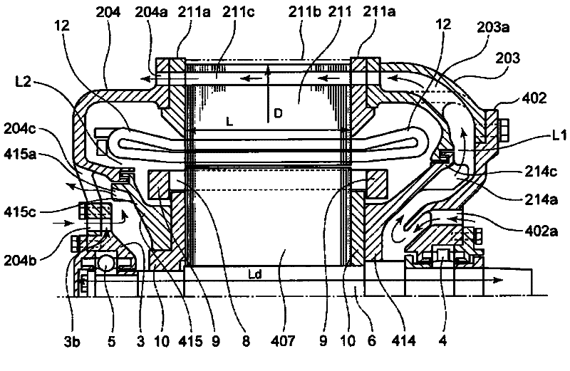
[0048] figure 1 It is a cross-sectional view of a fully enclosed main motor for a vehicle according to Embodiment 1 of the present invention.

[0049] On both sides of the stator core 211, core holding plates 211a, 211a are attached. A plurality of connection plates 211b are attached to a part of the entire outer circumference of the stator core 211 between the core holding plates 211a on both sides. A plurality of ventilation passages 211c are formed on the outer peripheral side of the stator core 211 by combining the plurality of connection plates 211b. A rotor core 407 and a ventilation fan 414 are attached to the rotor shaft 6 . The plurality of blades 214a are attached and arranged radially from the rotation axis at appropriate intervals in the circumferential direction of one surface of the fan main plate 214c of the ventilation fan 414 . The inner side of the fan main plate 214c extends to the vicinity of the inner peripheral side of the end ring 9 and is in close c...

Embodiment 2

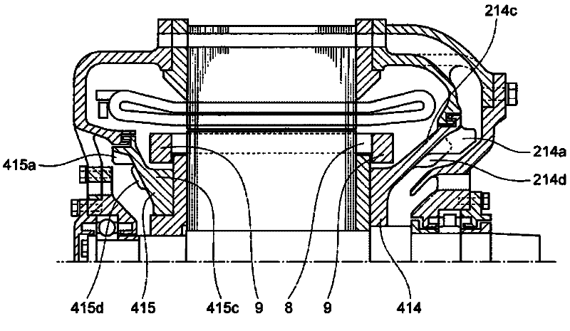
[0059] figure 2 It is a cross-sectional view of a fully enclosed main motor for a vehicle according to Embodiment 2 of the present invention. The Example 2 with figure 1 The difference of the illustrated embodiment 1 is that a cooling plate 214d is provided on the blade 214a side of the fan main board 214c of the ventilation fan 414, and a cooling plate 415d is provided on the blade 415a side of the fan main board 415c of the ventilation fan 415. The heat of the rotor (rotor bar 8, end ring 9) can be more effectively diffused to the outside by adding the heat sink 214a. A plurality of cooling plates 214d may be provided between adjacent blades 214a, or a cooling plate 214d may be provided or no cooling plate 214d may be provided between adjacent blades 214a. That is, the number, shape, and position of the heat sink 214d are not limited. In addition, a heat dissipation plate 415d is also provided on the outside of the ventilation fan 415, and its effect is basically the sa...

Embodiment 3

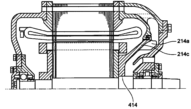
[0061] image 3 It is a cross-sectional view of a fully enclosed main motor for a vehicle according to Embodiment 3 of the present invention. The Example 3 with figure 1 The first exemplary embodiment shown differs in that the ventilation fan 415 on the side of the counter drive shaft is omitted. If sufficient cooling is achieved only by the ventilation fan 414 on the drive shaft side, there is no need to provide a ventilation fan on the counter drive shaft side. Furthermore, as shown in Embodiment 2, a cooling plate 214d may also be installed on the fan main board 214C.


PUM


Abstract

A totally-enclosed main motor for a vehicle comprises a stator core (211) and a rotor core (407) disposed on the inner peripheral side of the stator core, a first bearing (4) disposed at one end of the stator core (211), a second bearing (5) disposed at the other end of the stator core (211), a rotor shaft (6) to which the rotor core (407) is attached and which is rotatably supported by the first bearing (4) and the second bearing (5), a first ventilation path (211c) constituted on the outer peripheral portion of the stator core (211), a ventilation fan (414) which comprises a plurality of vanes (214a) and which is closely attached to the rotor core (407), and a second ventilation path for introducing the outside air from the inlet (402a) provided to a bearing bracket (402) to the portion near the rotor shaft (6). The cooling air flowing into the motor through the inlet (402a) is discharged from the second ventilation path (203a) to the outside of the motor via the outer peripheral portion of the ventilation fan (414) and the first ventilation path (211c) by the ventilation fan (414).

Description

technical field [0001] The present invention relates to a vehicle-use fully enclosed main motor for driving a railway vehicle. Background technique [0002] Generally, in a railway vehicle (hereinafter referred to as "vehicle"), a main motor (hereinafter referred to as "motor") is mounted on a trolley arranged under the car body, and the torque of the motor is transmitted through a coupling (coupling) and The gear unit transmits to the wheels to drive the vehicle. The existing structure of this motor is as follows: Figure 14 shown. Figure 14 The existing motor has a cylindrical frame 1 as a fixed part, a bearing bracket 2 is installed on one end side of the frame 1, and a housing 3 is installed on the center part of the other end side of the frame 1, and the bearing bracket 2 is used Both end portions of the rotor shaft 6 are rotatably supported by bearings 4 , 5 provided at respective central portions of the housing 3 . A rotor core 7 is fixed to the central portion in ...

Claims


Application Information

Patent Timeline
Patent Type & Authority Applications(China)
IPC IPC(8): H02K5/20H02K9/06
CPCH02K1/20H02K9/06H02K9/16H02K9/26H02K9/08H02K5/207H02K9/18H02K9/14
Inventor 永山孝白石茂智
Owner KK TOSHIBA
Why Eureka
Try Eureka