Magnetic resonance system and method for comprehensive implantable device safety tests and patient safety monitoring

An implanted device and magnetic resonance technology, applied in the field of magnetic resonance technology, can solve the problems of insecurity, increased complexity of the implanted device, and inability to detect local heating and the like

Inactive Publication Date: 2012-03-07
KONINK PHILIPS ELECTRONICS NV
View PDF2 Cites 8 Cited by
  • Summary
  • Abstract
  • Description
  • Claims
  • Application Information

AI Technical Summary

Problems solved by technology

For example, it increases the complexity of the implant and also only provides localized temperature measurement, possibly failing to detect localized heating of parts of the implant remote from the temperature sensor
Additionally, it is generally considered unsafe to allow implanted devices to heat inside a patient, archaeological mummified body, or other sensitive subject
As a result, by the time the temperature sensor detects heat, there may already be an unsafe condition

Method used


Image

  • Magnetic resonance system and method for comprehensive implantable device safety tests and patient safety monitoring
  • Magnetic resonance system and method for comprehensive implantable device safety tests and patient safety monitoring
  • Magnetic resonance system and method for comprehensive implantable device safety tests and patient safety monitoring

Examples


Embodiment Construction

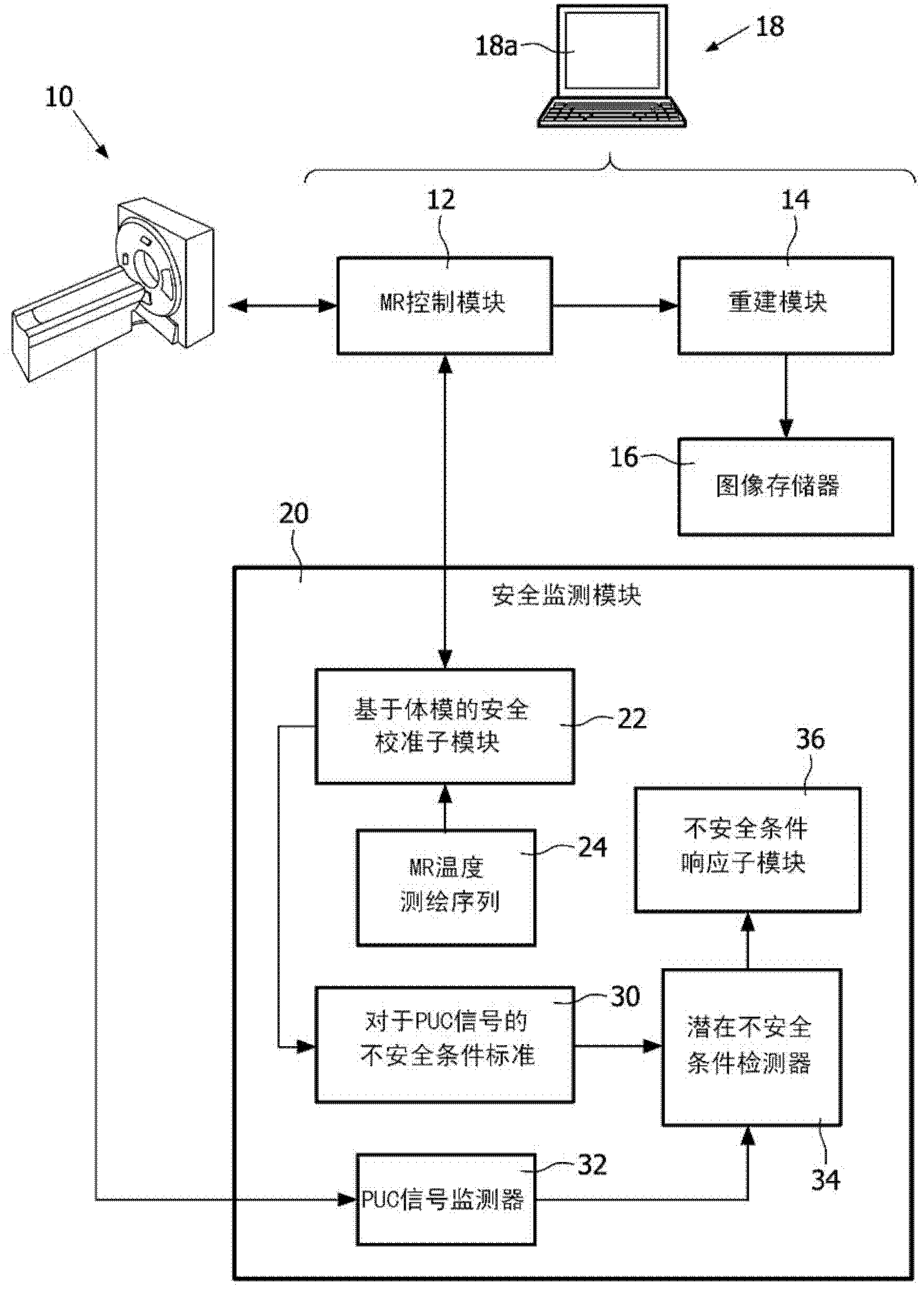
[0020] refer to figure 1 , the magnetic resonance system includes a magnetic resonance scanner 10, such as the illustrated Achieva TM Magnetic resonance scanner (available from Koninklijke Philips Electronics N.V., Eindhoven, The Netherlands) or Intera TM or Panorama TM A magnetic resonance scanner (both also available from Koninklijke Philips Electronics N.V.), or another commercially available magnetic resonance scanner or a non-commercial magnetic resonance scanner, etc. In an exemplary embodiment, the magnetic resonance scanner includes internal components (not shown), such as generating static (B 0 ) magnetic field superconducting or resistive main magnet, for superimposing the selected magnetic field gradient on the static magnetic field group of magnetic field gradient coil windings, for the selected (typically 1 H MRI, but also thought of as 1 H Magnetic resonance as an alternative or supplement to another magnetic resonance nucleus) Frequency generating radio freq...


PUM


Abstract

A magnetic resonance method comprises: performing (C1) a magnetic resonance procedure on a calibration subject including an implant device; detecting (C2) a pick-up coil (PUC) signal at least during a radio frequency transmit phase of operation (C1); performing (C3) three dimensional temperature mapping of the calibration subject using a magnetic resonance sequence configured to detect any temperature change induced in any part of the implant device by operation (C1); generating (C4) an unsafe condition criterion (30) for the detected PUC signal based on correlating a PUC signal characteristic detected by operation (C2) with a temperature change detected by operation (C3); performing (M5) the magnetic resonance procedure on a subject containing an implant device; detecting (M6) a PUC signal at least during a radio frequency transmit phase of operation (M5); and monitoring (M7) for an unsafe condition indicated by the PUC signal detected in operation (M6) satisfying the unsafe condition criterion (30).

Description

technical field [0001] The following relates to magnetic resonance techniques. The following have illustrative applications in magnetic resonance imaging and spectroscopy and are described with particular reference thereto. However, the following will apply to other magnetic resonance applications as well. Background technique [0002] A difficulty with the diagnostic or clinical application of magnetic resonance (MR) for imaging etc. is the incompatibility with certain implanted devices. Such implanted devices may be permanent or semi-permanent, such as cardiac pacemakers, orthopedic joint implants, etc.; or may be temporarily inserted implanted devices, such as interventional devices (eg, catheters or biopsy needles) . [0003] For purposes of MR safety, implants are generally classified as one of the following: "MR safe", which means that the implant does not contain metal or other conductive materials; "MR conditional", which means that the implant contains at least ...

Claims


Application Information

Patent Timeline
Patent Type & Authority Applications(China)
IPC IPC(8): G01R33/28
CPCG01R33/285G01R33/288
Inventor I·格雷斯林S·克吕格尔
Owner KONINK PHILIPS ELECTRONICS NV
Why Eureka
Try Eureka