
Method and device for controlling a vacuum apparatus

A negative pressure device and negative pressure technology, applied in the direction of pump control, mechanical equipment, pump/compressor arrangement, etc., can solve problems such as failure of negative pressure supply, and achieve simple design, best effect and strong effect Effect

Active Publication Date: 2012-03-14
FORD GLOBAL TECH LLC
View PDF6 Cites 4 Cited by
  • Summary
  • Abstract
  • Description
  • Claims
  • Application Information

AI Technical Summary

Problems solved by technology

From maximum working height, the opening threshold decreases to 0 bar and the pump can no longer be opened, which leads to a failure of the negative pressure supply

Method used


Image

  • Method and device for controlling a vacuum apparatus
  • Method and device for controlling a vacuum apparatus
  • Method and device for controlling a vacuum apparatus

Examples


Embodiment Construction

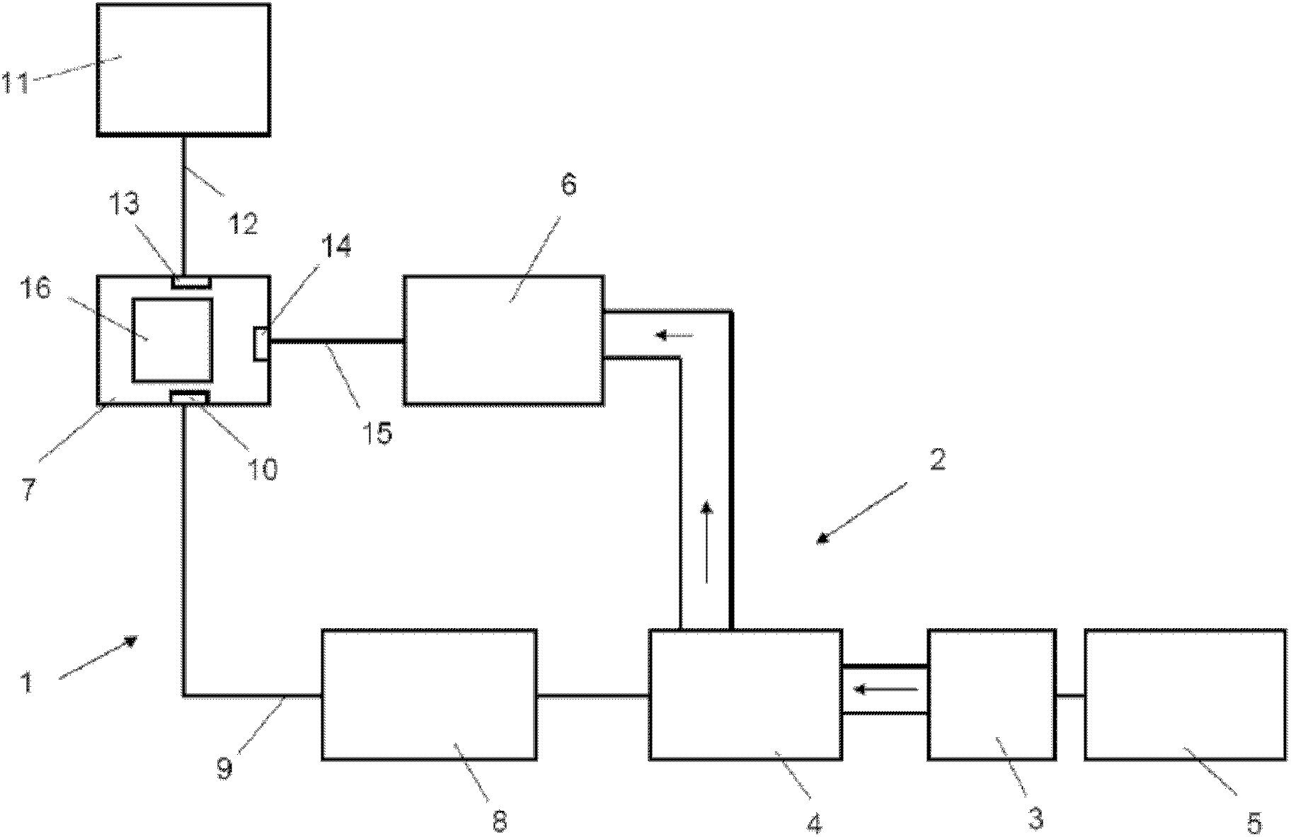
[0034] figure 1 A device 1 for controlling a vacuum device 2 of a pneumatic servo unit such as, for example, a vacuum brake booster 3 of a motor vehicle is shown. The vacuum device 2 has a vacuum accumulator 4 which is fluidically connected to a brake booster 3 which is activated by a brake pedal 5 . The negative pressure accumulator 4 is also fluidly connected to the intake manifold (not shown) of the motor vehicle engine. A line branches off from this connecting line to a pump 6, for example an electric suction pump. Usually a check valve is provided in the above connection line and only allows flow from said negative pressure accumulator 4 to said intake line. The pump 6 can apply negative pressure to the negative pressure accumulator 4 .

[0035] Airflow and its direction are indicated by arrows in the fluid lines. The negative pressure device 2 includes the negative pressure accumulator 4, the pump 6 and the fluid pipeline.

[0036] A controller 7 , such as for examp...


PUM


Abstract

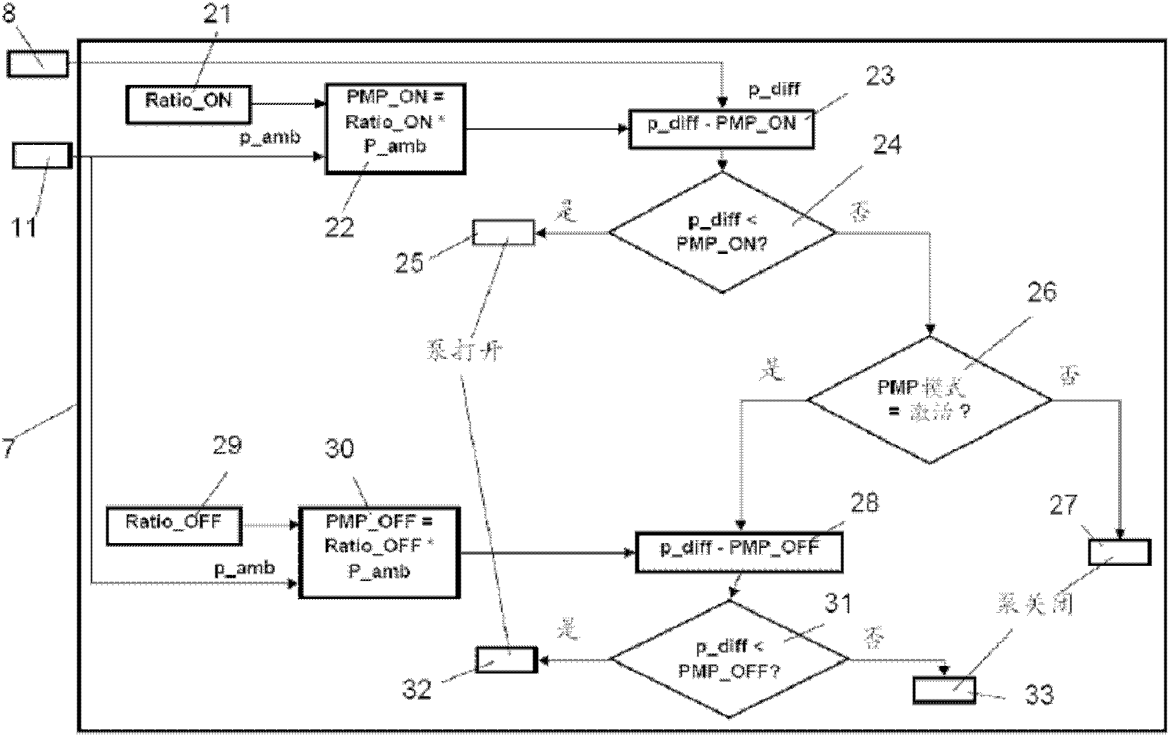
Method and device for controlling a vacuum apparatus. A method for controlling a vacuum apparatus that applies vacuum to a vacuum accumulator with a pump of a pneumatically operated servo unit of a motor vehicle. The method comprises the steps of determining the pressure in the vacuum accumulator; determining the ambient pressure; adapting a pump control signal to the ambient pressure; comparing the pressure in the vacuum accumulator with an adapted pump control signal; and outputting a pump actuation signal that is a function of the comparison.

Description

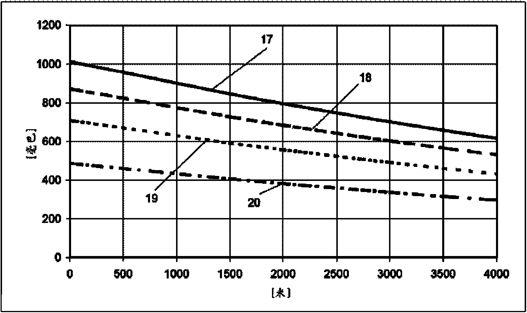
technical field [0001] The invention relates to a method for controlling a negative pressure device of a pneumatic servo unit of a motor vehicle, wherein the negative pressure is applied to a negative pressure accumulator by means of a pump. Background technique [0002] A negative pressure pump (on / off mode), which is controlled by a switch, changes its switch point as the ambient pressure changes, for example relative to changes in altitude. Therefore, with increasing altitude, the absolute "off" switch pressure controlled by the switch decreases, and necessarily from a certain altitude, it is no longer possible for the negative pressure pump to lower the predetermined absolute pressure. Turn off the pump. This means that from this point on the pump can no longer be switched off. The lower the absolute pressure at which the pump is shut off, the lower the maximum working height for such a failure event. If the pump reaches a minimum absolute pressure of 14% of ambient p...

Claims


Application Information

Patent Timeline
Patent Type & Authority Applications(China)
IPC IPC(8): B60T17/02F04B49/00
CPCF04B37/14F04B49/065F04B2205/03B60T17/02F04B49/06F04B2205/063F04B2207/02
Inventor R·施密德M·塔诺维斯基I·穆尔R·W·弗格森
Owner FORD GLOBAL TECH LLC
Learn More