Check patentability & draft patents in minutes with Patsnap Eureka AI!

Electronic device having antenna pattern embedded in case and method for manufacturing the same

An electronic device and antenna pattern technology, which is applied in the direction of antenna support/mounting device, antenna, antenna parts, etc., can solve the problems of increased manufacturing cost, reduced versatility, and reduced space utilization of the main circuit board.

Inactive Publication Date: 2012-03-14
SAMSUNG ELECTRO MECHANICS CO LTD
View PDF4 Cites 32 Cited by
  • Summary
  • Abstract
  • Description
  • Claims
  • Application Information

AI Technical Summary

Problems solved by technology

[0005] However, since each mobile communication terminal is designed to have different positions for matching circuits and antenna connection structures, when designing an antenna for such a function, the versatility is reduced, and since it is applied to an FPCB antenna to ensure antenna performance High-priced magnetic sheets lead to increased manufacturing costs
[0006] In addition, since a space for a matching circuit on the main circuit board must be secured in advance, the space utilization of the main circuit board is reduced

Method used


Image

  • Electronic device having antenna pattern embedded in case and method for manufacturing the same
  • Electronic device having antenna pattern embedded in case and method for manufacturing the same
  • Electronic device having antenna pattern embedded in case and method for manufacturing the same

Examples


Embodiment Construction

[0037] Now, exemplary embodiments of the present invention will be described in detail with reference to the accompanying drawings. However, this invention may be embodied in many different forms and should not be construed as limited to the embodiments set forth herein. Rather, these embodiments are provided so that this disclosure will be thorough and complete, and will fully convey the scope of the invention to those skilled in the art.

[0038] In the drawings, the shapes and dimensions may be exaggerated for clarity, and the same reference numerals will be used throughout to designate the same or like components.

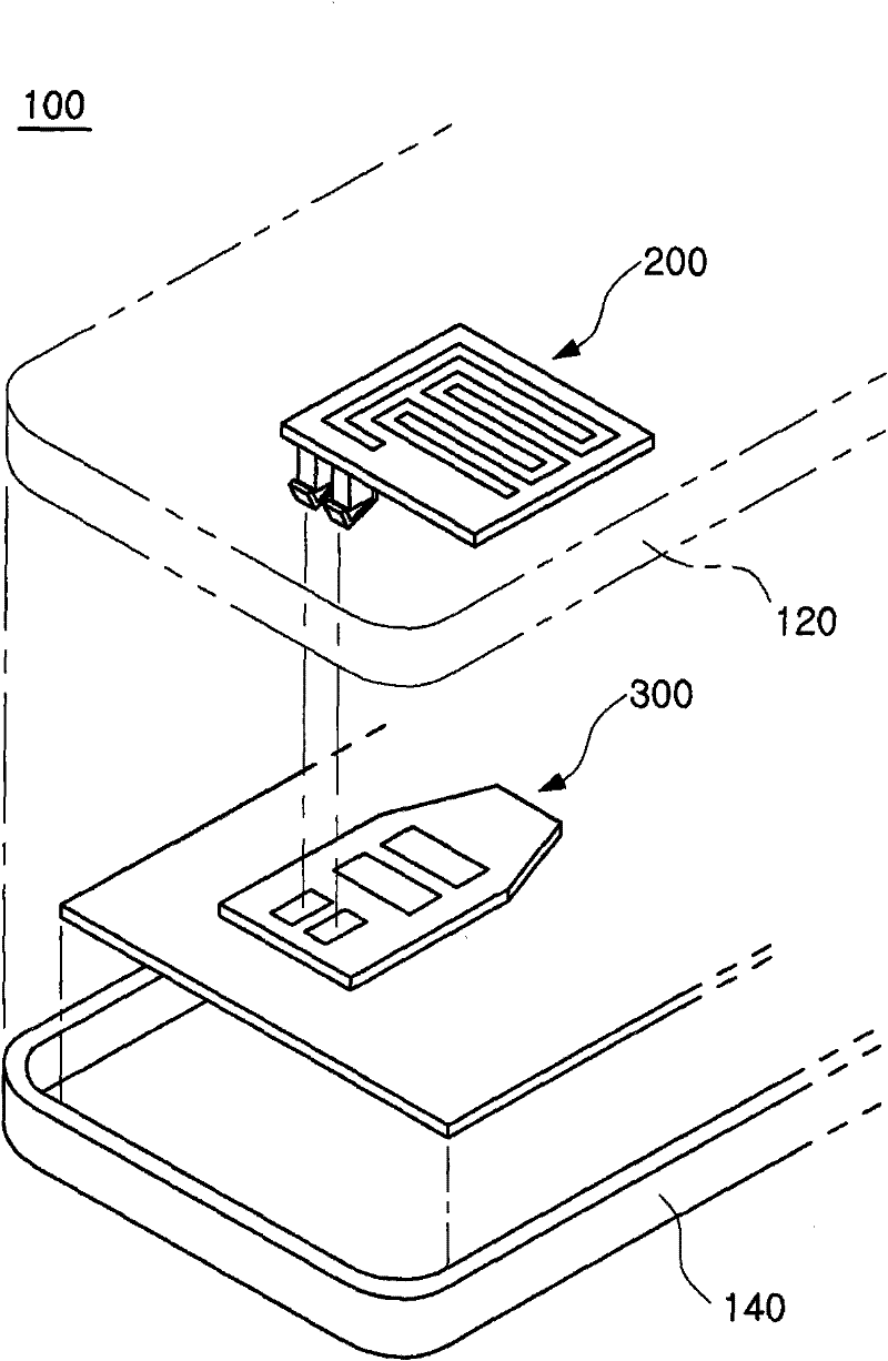
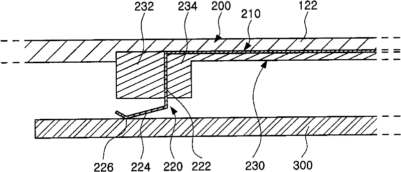
[0039] figure 1 is a partially cutaway exploded perspective view of the mobile communication terminal (ie, electronic device) according to the first exemplary embodiment of the present invention. figure 2 is a combined sectional view of a case of a mobile communication terminal (ie, an electronic device) and a USIM card according to the first exemplary embod...


PUM


Abstract

An electronic device (100) having an antenna pattern (210) embedded in a case and a method for manufacturing the same are provided. The electronic device includes: a radiator (210) embedded within a case (120,200) and having an antenna pattern part for transmitting and receiving a signal; a smart card (300) having a matching unit (320) for matching a signal between a main board separated from the case and the radiator and a connection pad (330) formed on one surface thereof to electrically connect the radiator and the matching unit; and a coupling member (220) having one end portion coupled to the radiator so as to be embedded within the case and the other end portion protruded from a lower surface of the case so as to be elastically in contact with the connection pad to allow the radiator and the matching unit to be electrically coupled.

Description

[0001] This application claims priority to Korean Patent Application No. 10-2010-0076105 filed with the Korean Intellectual Property Office on Aug. 6, 2010, the disclosure of which is hereby incorporated by reference. technical field [0002] The present invention relates to an electronic device in which an antenna pattern is embedded in a housing and a method for manufacturing the electronic device. Background technique [0003] Mobile communication terminals supporting wireless communication, such as mobile phones, personal digital assistants (PDAs), navigation devices, notebook computers, and the like, are indispensable devices in modern society. With the development of technology, various functions (for example, RFID (Radio Frequency Identification), NFC (Near Field Communication), GSM (Global System for Mobile Communications), UMTS (Universal Mobile Telecommunications System), GPRS (General Packet Radio Service), WCDMA (Wideband Code Division Multiple Access), WIFI (Wir...

Claims


Application Information

Patent Timeline
Patent Type & Authority Applications(China)
IPC IPC(8): H01Q1/22H01Q1/38H01P11/00H01Q1/24H01Q1/40
CPCB29C45/1671B29L2031/3456B29L2031/3481G06K19/07741H01Q1/243H01Q1/38H01Q1/40H01Q1/405
Inventor 张基源成宰硕洪河龙李大揆金泰成韩昌穆南炫吉全大成李得雨苏源煜
Owner SAMSUNG ELECTRO MECHANICS CO LTD
Features
  • R&D
  • Intellectual Property
  • Life Sciences
  • Materials
  • Tech Scout
  • Unparalleled Data Quality
  • Higher Quality Content
  • 60% Fewer Hallucinations
Learn More