Drawer self-locking mechanism of tool box cabinet

A technology of drawers and cabinets, which is applied in building locks, building structures, buildings, etc., can solve problems such as insecurity, and achieve reliable self-locking and simple overall structure

Active Publication Date: 2012-11-21
常熟中诚工具箱柜有限公司
View PDF6 Cites 3 Cited by
  • Summary
  • Abstract
  • Description
  • Claims
  • Application Information

AI Technical Summary

Problems solved by technology

Taking the position shown in the figure as an example, fix the locking piece seat 1 to the outside of the drawer backboard with a pair of screws when in use. When the box is pushed in the direction of the box body, the sliding surface of the lock hook 2 contacts the lock bar preset on the box body, so that the lock hook 2 moves upwards, and when the lock hook 2 passes over the lock bar on the box body Just drop automatically after the hole on the top, thereby embodies self-locking function, although this self-locking device has the advantage of very simple structure, but, because the locking plate hook 2 is arranged on the locking plate seat 1 through the pin shaft, and because the pin shaft Corresponding to the long groove of the lock hook 2, so when the toolbox is tilted or even stretched at a certain angle, for example, after the toolbox is stretched 90°, the lock hook 2 will face the opposite direction to the previous locking on the pin shaft under the action of its own weight Move, so that the lock bar on the box body loses its resistance to the lock piece hook 2, and the drawer can be pulled out, which is unsafe

Method used


Image

  • Drawer self-locking mechanism of tool box cabinet
  • Drawer self-locking mechanism of tool box cabinet
  • Drawer self-locking mechanism of tool box cabinet

Examples


Embodiment

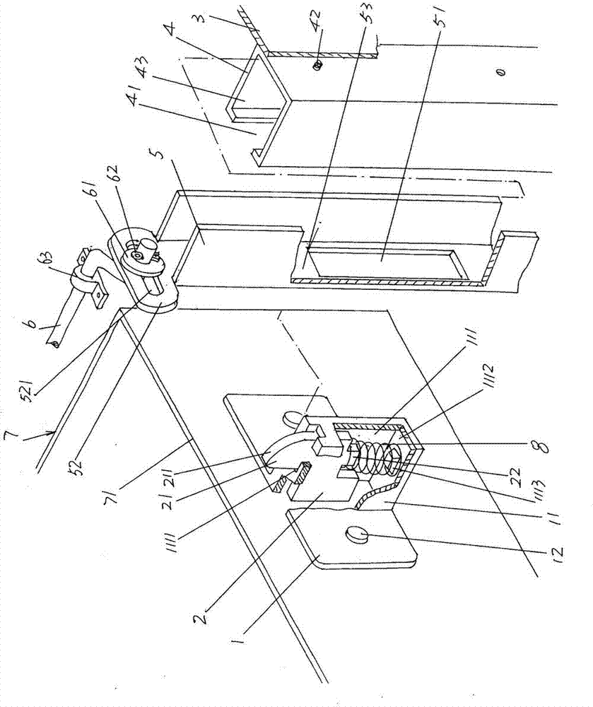
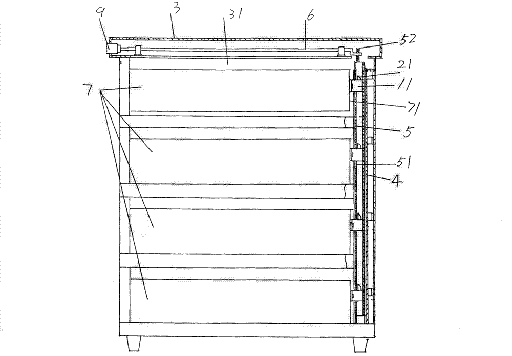
[0020] please see figure 1 , shows the box body 3 of toolbox cabinet, on this box body 3 and towards the side of the drawer 7 that also mentions below is fixed with a guide rail tube 4 with fixing screw 42, and the height direction of guide rail tube 4 has guide rail tube Cavity 43, and a groove chamber 41 communicated with guide rail lumen 43 is offered on the side of the guide rail tube 4 facing the drawer 7. As shown in the figure, the cross-sectional shape of the whole guide rail tube 4 is a door shape on the body.

[0021] A lock bar 5 with a door-shaped cross section is slidably accommodated in the guide rail lumen 43 of the guide rail tube 4 , and a lock plate hook hole 51 is opened on the lock bar 5 and also faces the side of the drawer 7 . According to common knowledge, on a box body 3, can be configured from top to bottom or bottom to top, for example by a plurality of figure 2 The schematically illustrated four drawers 7 therefore have locking plate hook hole...


PUM


Abstract

The invention relates to a drawer self-locking mechanism of a tool box cabinet, belonging to the technical field of hardware appliances. The tool box cabinet comprises a box body, a guide rail pipe, a locking bar, a key driving locking shaft and drawers, wherein the guide rail pipe is fixed at one side of the box body towards the drawer; the locking bar is matched with the guide rail pipe in a sliding manner and is provided with locking piece hook holes; the key driving locking shaft is arranged on the box body in a pivoted manner and is connected with the locking bar; the drawers are matchedwith drawer cavities of the box body in an inserting and pulling manner; drawer back plates of the drawers face to the locking bar; the drawer self-locking mechanism comprises locking piece seats andlocking piece hooks; each locking piece seat is fixed at one side of each drawer back plate towards the locking bar and corresponds to each locking piece hook hole; and the locking piece hooks are arranged on the locking piece seats in a matching manner and are matched with the locking piece hook holes. The drawer self-locking mechanism is characterized by also comprising a spring; and one end ofthe spring is arranged on the locking piece seat in a bearing manner, and the other end of the spring is arranged on the locking piece hook in a bearing manner. The drawer self-locking mechanism has the advantages of locking safety, simple whole structure, convenient installation and use and good matching with the box body.

Description

technical field [0001] The invention belongs to the technical field of hardware appliances, and in particular relates to a drawer self-locking mechanism of a tool box cabinet. Background technique [0002] The toolbox cabinet lockset disclosed by Chinese Invention Patent Publication No. CN101672133A has eliminated prior patents such as CN1573002A (toolbox rotary latch), CN2258219Y (toolbox lockset), CN2758032Y (toolbox with a lock structure) and CN2705278Y (toolbox Fastener structure) objectively embodies the various technical effects summarized in the first paragraph on page 3 of the manual, including the self-locking function. But there is a shortcoming that the structure is relatively complicated. [0003] China Design Patent Authorization Announcement No. CN3341116S discloses the structure as image 3 The drawer self-locking mechanism shown includes a cleat seat 1 and a cleat hook 2. A long groove is opened on the cleat hook 2, and the cleat hook 2 is matched with the c...

Claims


Application Information

Patent Timeline
Patent Type & Authority Patents(China)
IPC IPC(8): E05B65/46E05B65/463
Inventor 王卫东
Owner 常熟中诚工具箱柜有限公司
Why Eureka
Try Eureka