Cap type ratchet self-locking device and steel support comprising same

A technology of self-locking device and steel support, which is applied in the field of steel support and can solve problems such as servo steel support failure and major accidents

Pending Publication Date: 2018-12-11
SHANGHAI HIGHWAY BRIDGE (GRP) CO LTD
View PDF0 Cites 1 Cited by
  • Summary
  • Abstract
  • Description
  • Claims
  • Application Information

AI Technical Summary

Problems solved by technology

[0006] The technical problem to be solved by the present invention is to provide a cap-type ratchet self-locking device and a steel support containing it in order to overcome the defect that the servo steel support in the prior art will fail and cause major accidents

Method used


Image

  • Cap type ratchet self-locking device and steel support comprising same
  • Cap type ratchet self-locking device and steel support comprising same
  • Cap type ratchet self-locking device and steel support comprising same

Examples


Embodiment 1

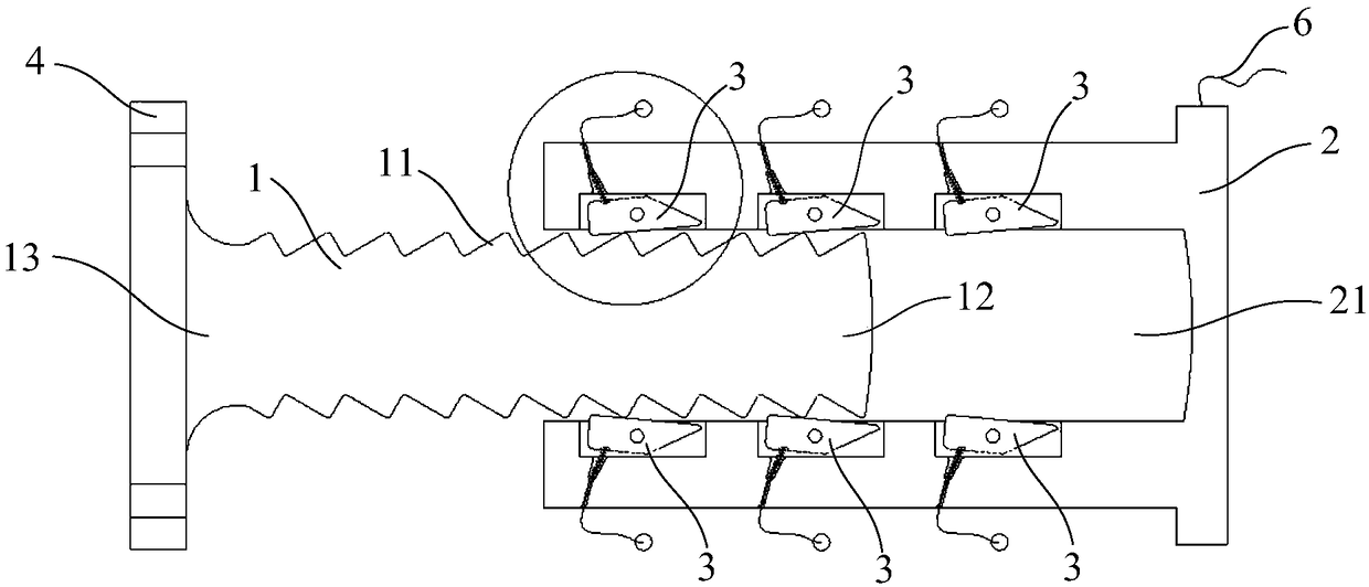
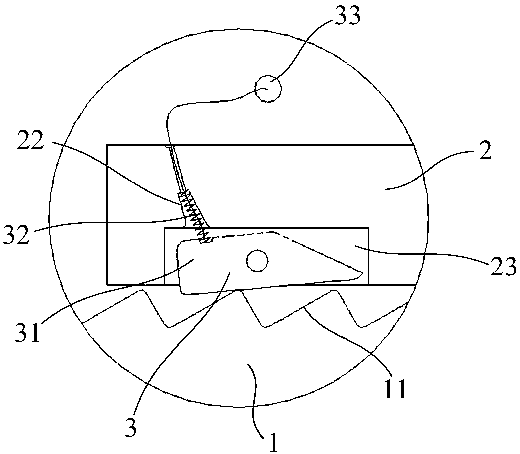
[0058] like Figure 1 to Figure 4 As shown, the cap type ratchet self-locking device of the present invention comprises an inner pin 1, a cap 2 and several wedge assemblies 3, the outer peripheral surface of the inner pin 1 is provided with a plurality of ratchets 11, and the ratchets 11 are arranged axially along the inner pin 1; the cap One end of 2 is provided with a mounting hole 21, the inner pin 1 can be inserted into the mounting hole 21, and the stop direction of the ratchet 11 is the direction in which the inner pin 1 is inserted into the mounting hole 21; several wedge assemblies 3 are arranged on the inner peripheral surface of the mounting hole 21 , the wedge assembly 3 includes a wedge 31, an elastic member 32 and a pull cable 33, the wedge 31 can rotate relative to the cap 2 and switch between the two states of deployment and retraction; when the wedge 31 is deployed, the wedge 31 can cooperate with the ratchet 11; when the wedge 31 retracts, the minimum distance...

Embodiment 2

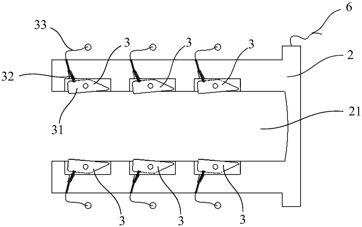
[0071] like Figure 7 to Figure 10 Shown is a schematic structural view of Embodiment 2 of the cap-type ratchet self-locking device of the present invention. The structure of the cap-type ratchet self-locking device of this embodiment is basically the same as that of Embodiment 1 except the cap 2. The mounting hole 21 of the cap 2 in this embodiment is not provided with an accommodating cavity 23, and the overall diameter of the inner peripheral surface of the mounting hole 21 is relatively large, and the support frame 5 can be installed on the inner peripheral surface of the mounting hole 21, and the wedge 31 is hinged on the The support frame 5 can also be rotated and switched between the two states of unfolding and retracting. The block cap 2 of this structure has a simple processing form and is easy to install.

[0072] like Figure 11 to Figure 12 Shown is a steel support with the above-mentioned cap-type ratchet self-locking device, and the method of applying the abov...


PUM


Abstract

The invention provides a cap type ratchet self-locking device and a steel support comprising the same. The cap type ratchet self-locking device comprises an inner pin, a cap and a plurality of wedge block assemblies, wherein a plurality of ratchets are arranged on the outer peripheral surface of the inner pin, a mounting hole is formed in one end of the cap, the inner pin can be inserted into themounting hole, the plurality of wedge block assemblies are arranged on the inner peripheral surface of the mounting hole, the wedge block assemblies comprise wedge blocks, elastic pieces and inhaul cables, the wedge blocks can rotate relative to the cap and can be switched between the two states of extension and retraction, one ends of the inhaul cables are fixed to the wedge blocks, the other ends of the inhaul cables extend out to the outside of the cap, and the inhaul cables can pull the wedge blocks to be in the retraction state. According to the cap type ratchet self-locking device and the steel support comprising the same, due to the fact that the wedge blocks cooperate with the ratchets, the cap cannot be retracted towards the direction of the inner pin, reliable self-locking can beachieved after installation is completed, only the inhaul cables need to be pulled during mounting or dismounting for achieving mounting ordismounting can be achieved, so that mounting and dismounting are both very convenient.

Description

technical field [0001] The invention relates to a cap type ratchet self-locking device. [0002] The present invention also relates to a steel support comprising the above cap type ratchet self-locking device. Background technique [0003] Steel support is a commonly used support structure in deep foundation pit engineering. It has the advantages of light weight, on-site assembly, fast and convenient installation and removal, can play a supporting role after installation, and can be reused. It is widely used in soft soil In strip and rectangular deep foundation pits. With the development of society, the development of underground space has gradually increased, a large number of deep foundation pit projects have appeared, and the amount of steel support has also shown an increasing trend year by year. However, the steel support is a flexible support, and its stiffness is much smaller than that of the concrete support, and the deformation generated during the stress process ...

Claims


Application Information

Patent Timeline
IPC IPC(8): E02D17/04
CPCE02D17/04
Inventor 陶利贾尚华陈辉郑诚王琰
Owner SHANGHAI HIGHWAY BRIDGE (GRP) CO LTD
Why Eureka
Try Eureka