Cleaner

A vacuum cleaner and filter technology, applied in the direction of vacuum cleaners, cleaning filter devices, cleaning equipment, etc., can solve problems such as reduced suction, clogged suction units, abnormalities, etc.

Active Publication Date: 2014-11-12
MAKITA CORP
View PDF6 Cites 0 Cited by
  • Summary
  • Abstract
  • Description
  • Claims
  • Application Information

AI Technical Summary

Problems solved by technology

[0006] However, in the vacuum cleaner in Patent Document 1, since the valve body operates to open the opening of the housing during use (during the operation of the air suction unit), external dust intrudes into the inside of the filter through the opening to cause clogging or suction. Unusual hazards of gas units
And because the pressure on the inside of the filter temporarily rises, the attraction force also decreases

Method used


Image

  • Cleaner
  • Cleaner

Examples


Embodiment Construction

[0015] Embodiments of the present invention will be described below based on the drawings.

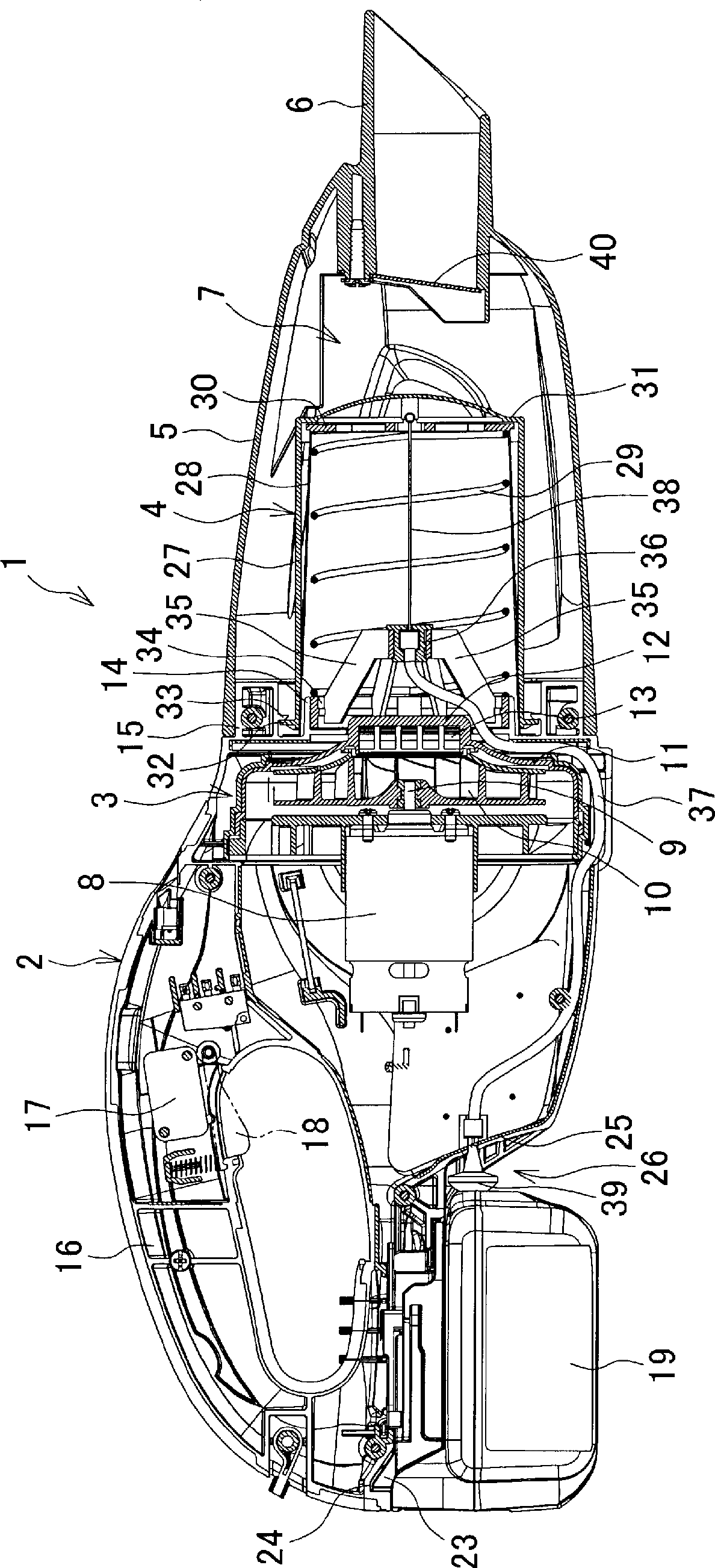
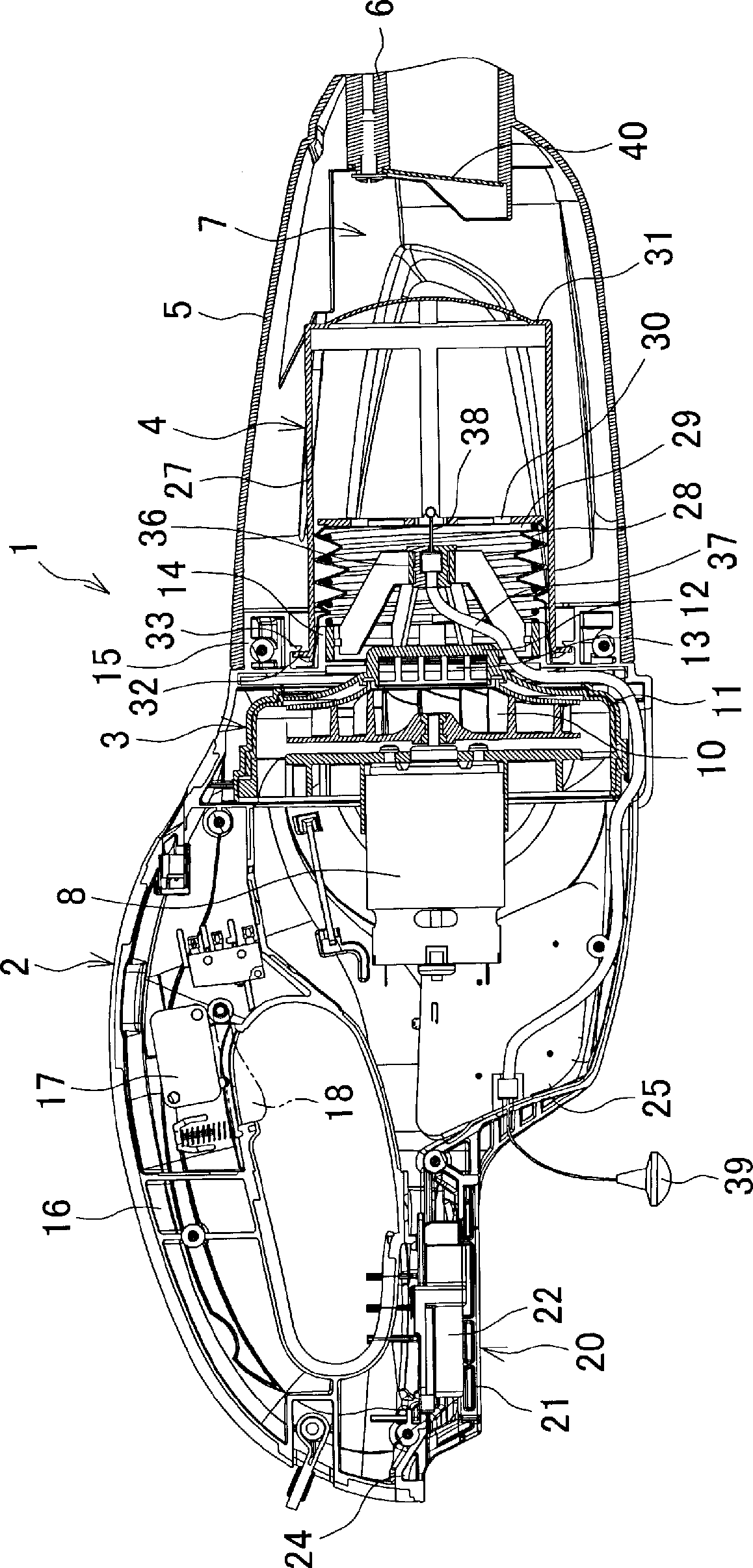
[0016] figure 1 It is a longitudinal sectional view of a rechargeable vacuum cleaner (hereinafter referred to as "vacuum cleaner"). The vacuum cleaner 1 accommodates the suction unit 3, and the front surface (referred to as figure 1 The right side is the front) the main body casing 2 of the filter unit 4 protrudes, and the capsule-shaped front side casing 5 is installed. The front side casing 5 has a cylindrical suction port 6 at the front end and forms a dust collection chamber inside. 7.

[0017] The suction unit 3 is formed so that the suction fan 10 fixed to the output shaft 9 of the motor 8 is covered with a cover 11, and the central part 12 of the cover 11 protrudes forward from the center of the front surface of the main body case 2 to form a suction port. 13. On the front surface of the main body casing 2, an inner ring 14 coaxially surrounding the central portion 12 and prot...


PUM


Abstract

A cleaner configured in such a manner that dust removal operation can be optimally performed without the removal of a front housing, without the entry of dust into the filter due to the dust removal operation, and without a decrease in the suction force. A cleaner (1), wherein a coiled spring (29) for pressing a filter (28) so that the filter is retained in an extended attitude is provided within the filter (28) of a filter unit (4), a mounting plate (30) is secured to the front end of the filter (28), one end of a wire (38) is connected to the mounting plate (30), and the other end of the wire (38) is led out of the inside of the filter (28) to the outside at the rear of the body housing after being made to pass through the body housing (2). The filter (28) can be arbitrarily contracted by causing, through pulling operation of the other end of the wire (38), the mounting plate (30) to recede against the pressing force of the coiled spring (29).

Description

technical field [0001] The invention relates to a vacuum cleaner which attracts dust and stores it. Background technique [0002] In a conventional vacuum cleaner, an air suction unit having a suction fan rotated by a motor is accommodated in a main body case, and a front side case having a suction port and forming a dust collection chamber inside is detachably attached to the front of the main body case. body, and block the suction port of the suction unit with a filter. Therefore, by the operation of the suction unit, the outside air is sucked in from the suction port, and the outside air is discharged from the exhaust port provided on the main body casing through the filter, so that the dust sucked in together with the outside air can be captured by the filter and coexist. The dust collection chamber accumulated in the front housing. [0003] In such a vacuum cleaner, if dust adheres to the surface of the filter and clogs the filter, the suction force will decrease and ...

Claims


Application Information

Patent Timeline
Patent Type & Authority Patents(China)
IPC IPC(8): A47L9/20
CPCA47L5/24A47L9/106
Inventor 长坂英纪
Owner MAKITA CORP
Why Eureka
Try Eureka