Pneumatic tire

一种充气轮胎、轮胎的技术,应用在轮胎零部件、轮胎胎面/胎面花纹、运输和包装等方向,能够解决很难兼顾、操纵稳定性和抗不均匀磨损性变差、花纹块刚性降低等问题,达到提高排水性、确保抗不均匀磨损性、确保操纵稳定性的效果

Inactive Publication Date: 2012-04-18
SUMITOMO RUBBER IND LTD
View PDF5 Cites 13 Cited by
  • Summary
  • Abstract
  • Description
  • Claims
  • Application Information

AI Technical Summary

Problems solved by technology

[0003] However, the above-mentioned methods are all accompanied by a reduction in the rigidity of the blocks, so there is a problem that handling stability and uneven wear resistance tend to be deteriorated
In this way, there is an antinomy relationship between improving water drainage and ensuring the rigidity of the block, so it is difficult to achieve both

Method used


Image

  • Pneumatic tire
  • Pneumatic tire
  • Pneumatic tire

Examples


Embodiment Construction

[0027] Hereinafter, one embodiment of the present invention will be described based on the drawings.

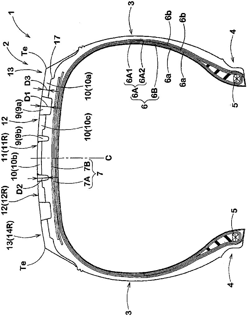
[0028] Such as figure 1 As shown, the pneumatic tire 1 of the present embodiment has a carcass 6 extending from the tread portion 2 to the bead core 5 of the bead portion 4 through the sidewall portion 3 ; and a belt layer 7 arranged on the carcass 6 On the outside in the radial direction and inside the tread portion 2 , a tire for a small truck is shown in this embodiment.

[0029] The above carcass 6 has, for example, a so-called 2-1 structure composed of two folded cords 6A and one turned cord 6B disposed outside the folded cords 6A.

[0030] The folded cord 6A is composed of an inner folded cord 6A1 disposed inside in the tire radial direction at the position of the tire equator C, and an outer folded cord 6A2 disposed outside the folded cord 6A1. Each of the folded cords 6A1 and 6A2 includes: an annular main body portion 6a extending from the tread portion 2 through th...


PUM


Abstract

A pneumatic tire (1) comprises a tread portion provided along each tread edge with shoulder blocks (14) defined by a circumferentially extending shoulder main groove (9a) and shoulder lateral grooves (10a) extending from the shoulder main groove to the tread edge. The shoulder main groove (9a) is made up of groove segments (15) curved convexly toward the tire equator. The shoulder lateral grooves (10a) extend at 45 to 90 degrees with respect to the tire circumferential direction, and are coupled with the first inclined parts (15a) of the groove segments (15). The shoulder blocks (18) are each subdivided by a shoulder sub groove extending at an angle of from 15 to 45 degrees with respect to the tire circumferential direction. The shoulder sub groove has an axially outer end (18a) connected with the shoulder lateral groove (10a) and an axially inner end (18b) coupled with the second inclined part (15b).

Description

technical field [0001] The present invention relates to a pneumatic tire that improves drainage while maintaining steering stability and uneven wear resistance by improving the shape of grooves and blocks formed in shoulder portions. Background technique [0002] There is known a pneumatic tire having a block pattern in which a plurality of blocks are formed on a tread portion. In recent years, it is expected that the drainage performance of the pneumatic tire will be further improved. In order to improve water drainage, it is necessary to smoothly drain the water film between the tread portion and the road surface to the ground contact edge side. Conventionally, in order to improve water drainage, for example, a method of increasing the width and / or depth of shoulder lateral grooves connected to the ground contact edge of the tread portion is known. [0003] However, the above-mentioned methods are all accompanied by a reduction in the rigidity of the blocks, so there is ...

Claims


Application Information

Patent Timeline
Patent Type & Authority Applications(China)
IPC IPC(8): B60C11/11B60C11/04
CPCB60C2011/0369B60C2011/0381B60C2011/0365B60C11/0302B60C11/11B60C2011/0346Y10S152/03Y10S152/902B60C11/01B60C11/04B60C11/13
Inventor 川内保范
Owner SUMITOMO RUBBER IND LTD
Why Eureka
Try Eureka