Multi-point identification method and system of infrared touch screen
An infrared touch screen, multi-point recognition technology, applied in the input/output process of data processing, instruments, electrical digital data processing and other directions, can solve the problem of time-consuming and other
- Summary
- Abstract
- Description
- Claims
- Application Information
AI Technical Summary
Problems solved by technology
Method used
Image
Examples
Embodiment approach 1
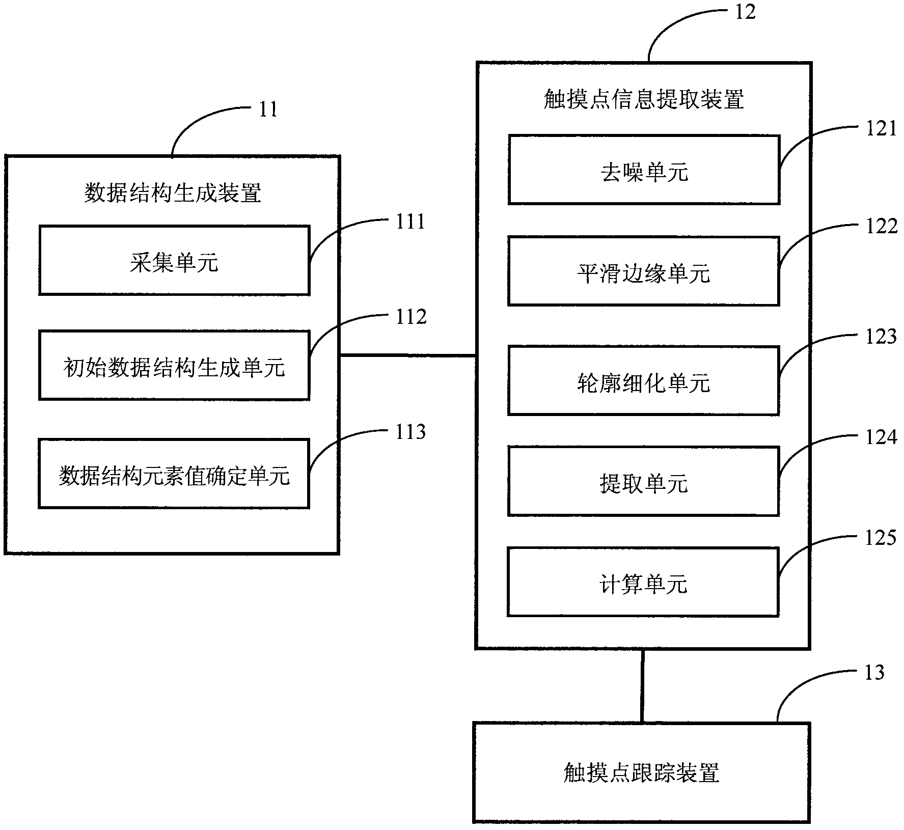
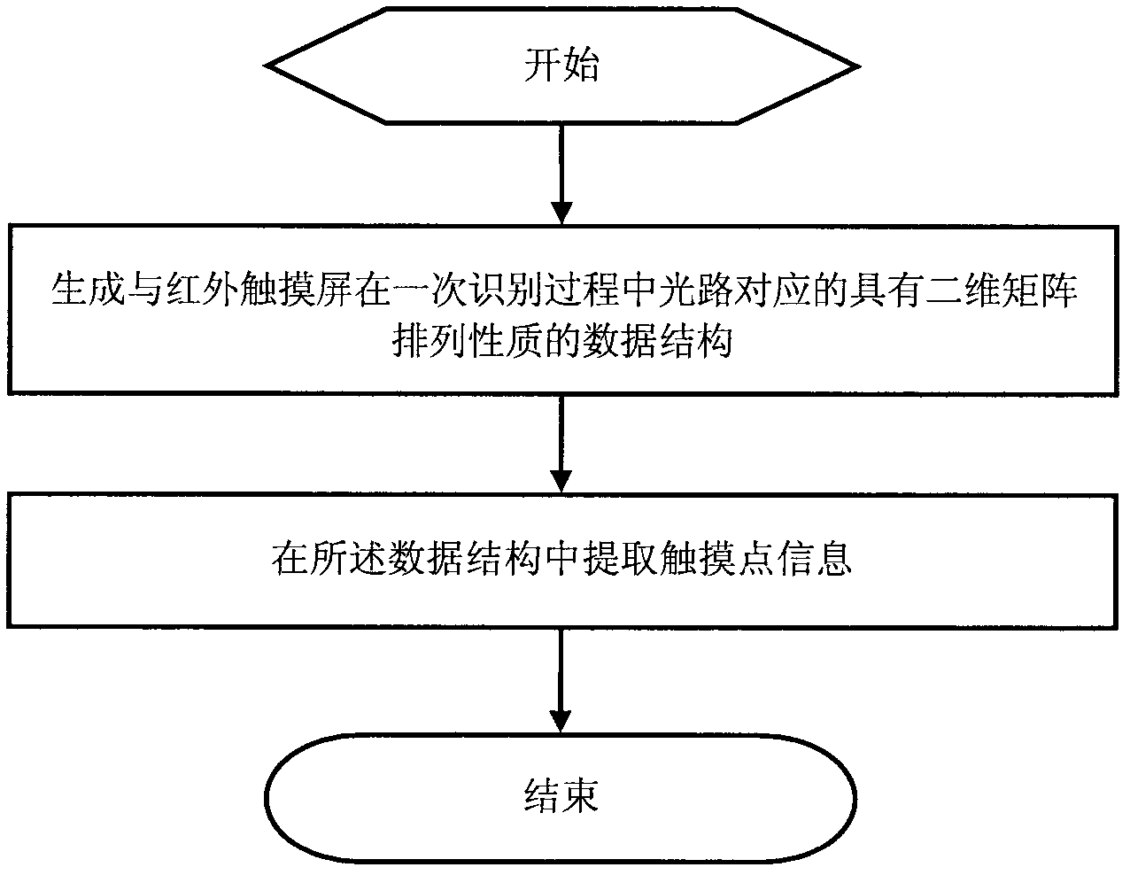
[0075] This embodiment describes a multi-point recognition system and method for an infrared touch screen. Such as figure 1 As shown, the system includes a data structure generation device 11 , a touch point information extraction device 12 and a touch point tracking device 13 . Wherein, the data structure generation device 11 includes a collection unit 111, an initial data structure generation unit 112, and a data structure element value determination unit 113, and the touch point information extraction device 12 includes a denoising unit 121, a smoothing edge unit 122, an outline refinement unit 123, Extraction unit 124 and calculation unit 125 .
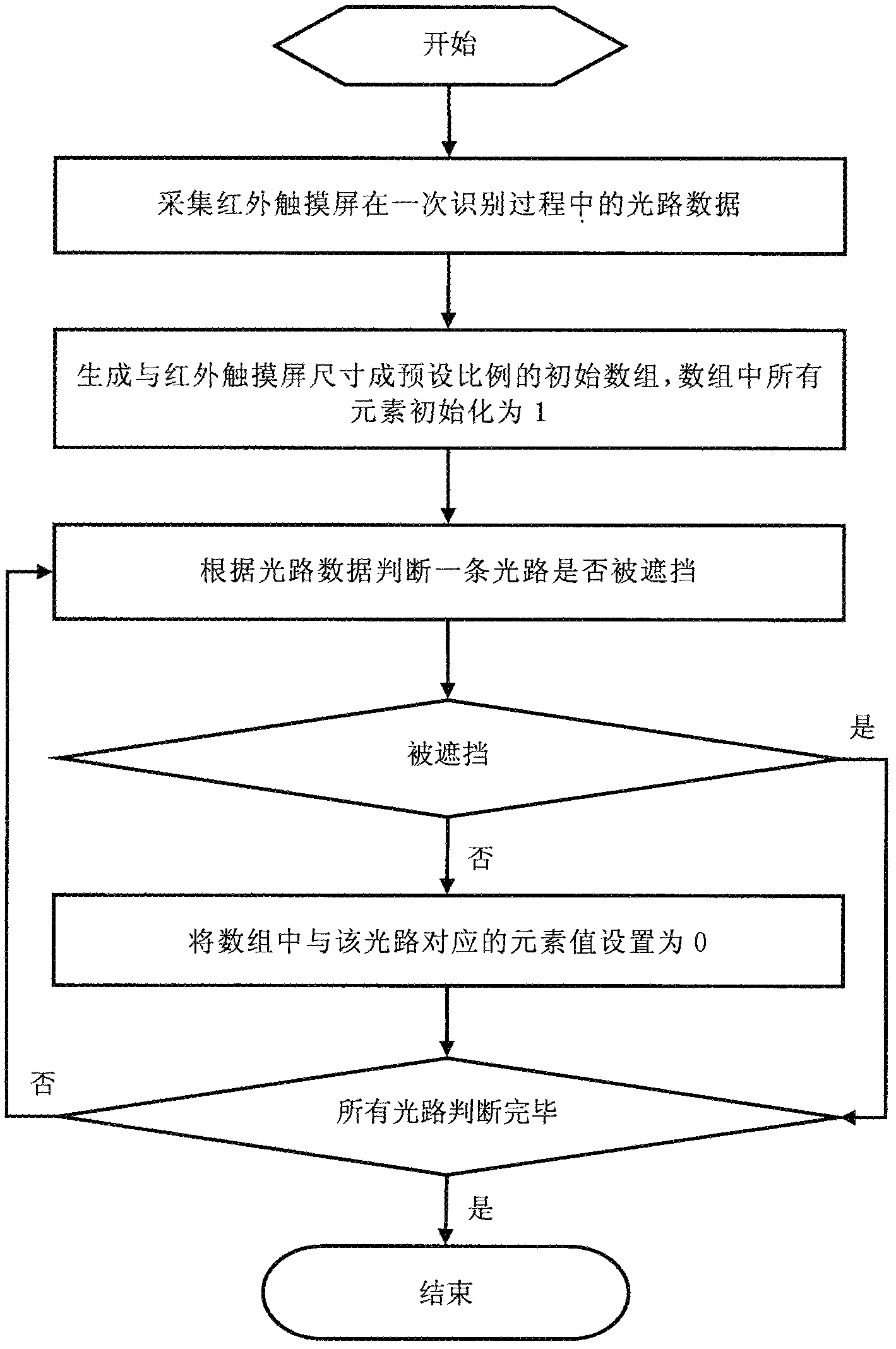
[0076] The data structure generation device 11 is used to generate a data structure with a two-dimensional matrix arrangement property corresponding to the optical path of the infrared touch screen during a recognition process. Wherein the acquisition unit 111 is used to collect the optical path data of the infrared touch screen...
Embodiment approach 2
[0124] In Embodiment 1, each step processes the entire array. Since the approximate position of each touch point area can be quickly obtained through the initial optical path data, the rough area set of the touch point can be obtained first, and subsequent operations are only performed on these areas. In this way, the processing speed will be greatly improved, but the basic idea is the same as that of Embodiment 1. The specific process is as follows:
[0125] First, an initial array with a preset ratio M to the size of the infrared touch screen is generated, and its element values are all 0. The rough areas of the candidate touch points are calculated according to the optical path data, which are approximately rectangular areas. For this, as Figure 11 As shown, on the basis of the first embodiment, the system of this embodiment adds a touch point area determination device 14 . If no candidate touch point area is obtained after calculation based on the optical path data,...
Embodiment approach 3
[0130] Since there is not necessarily a touch operation during a recognition process, if no touch operation occurs during a recognition process, it is not necessary to perform the same process as described in Embodiment 1 or 2, but it will also occupy system resources. , leading to a decrease in recognition efficiency.
[0131] Such as Figure 13 and 14 As shown, in this embodiment, on the basis of Embodiment 1 or Embodiment 2, a pre-judgment device 15 is added to pre-judge whether a touch point exists according to the optical path data. The specific judgment method may adopt any method in the prior art, which will not be repeated here.
[0132] In a recognition process, after the optical path data is collected, the pre-judgment device first judges whether there is a touch point according to the optical path data. If there is no touch point, this identification is ended; if there is a touch point, then the method in Embodiment 1 or Embodiment 2 is used to identify the touch...
PUM
 Abstract
Description
Claims
Application Information
 - R&D
- Intellectual Property
- Life Sciences
- Materials
- Tech Scout
- Unparalleled Data Quality
- Higher Quality Content
- 60% Fewer Hallucinations
Browse by: Latest US Patents, China's latest patents, Technical Efficacy Thesaurus, Application Domain, Technology Topic, Popular Technical Reports.
© 2025 PatSnap. All rights reserved.Legal|Privacy policy|Modern Slavery Act Transparency Statement|Sitemap|About US| Contact US: help@patsnap.com


