Luminescence module

A light-emitting module and light source technology, applied in the direction of optics, light guide, electric light source, etc., can solve the problems of material cost, uneven light output on the light output surface, etc., and achieve the effect of improving linear bright lines and uniform light output brightness

Inactive Publication Date: 2012-04-25
SHANGHAI XIANGLONG ELECTRONICS TECH
View PDF9 Cites 8 Cited by
  • Summary
  • Abstract
  • Description
  • Claims
  • Application Information

AI Technical Summary

Problems solved by technology

When the light guide plate emits light, the position of the light-emitting surface corresponding to each linear groove or convex line will display multiple corresponding linear bright lines, resulting in uneven light emission on the light-emitting surface as a whole. More optical cover sheets must be used to compensate , which consumes a lot of material cost and needs to be further improved

Method used


Image

  • Luminescence module
  • Luminescence module
  • Luminescence module

Examples


Embodiment Construction

[0031] Below in conjunction with accompanying drawing and specific embodiment the present invention is described in further detail:

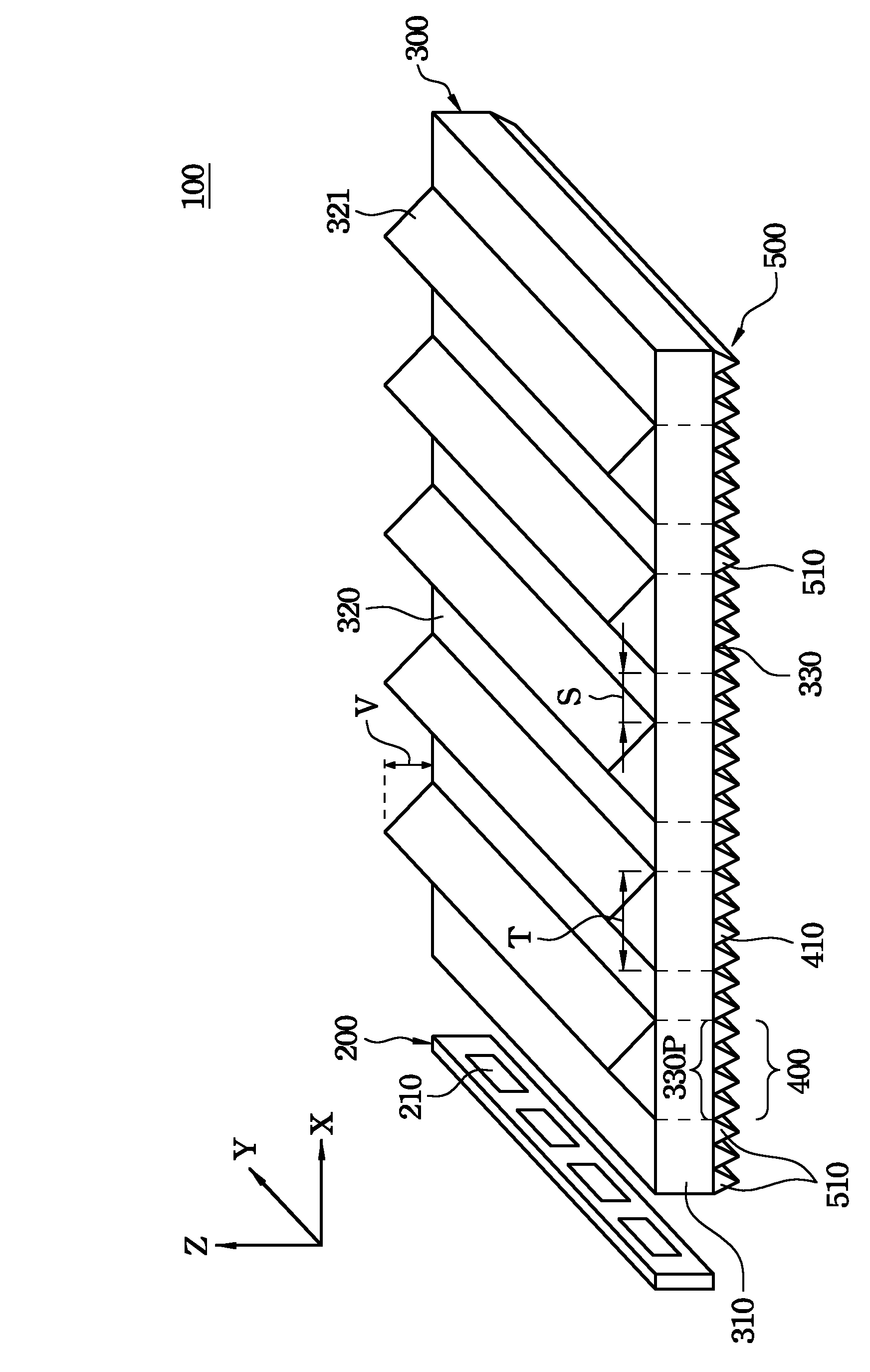
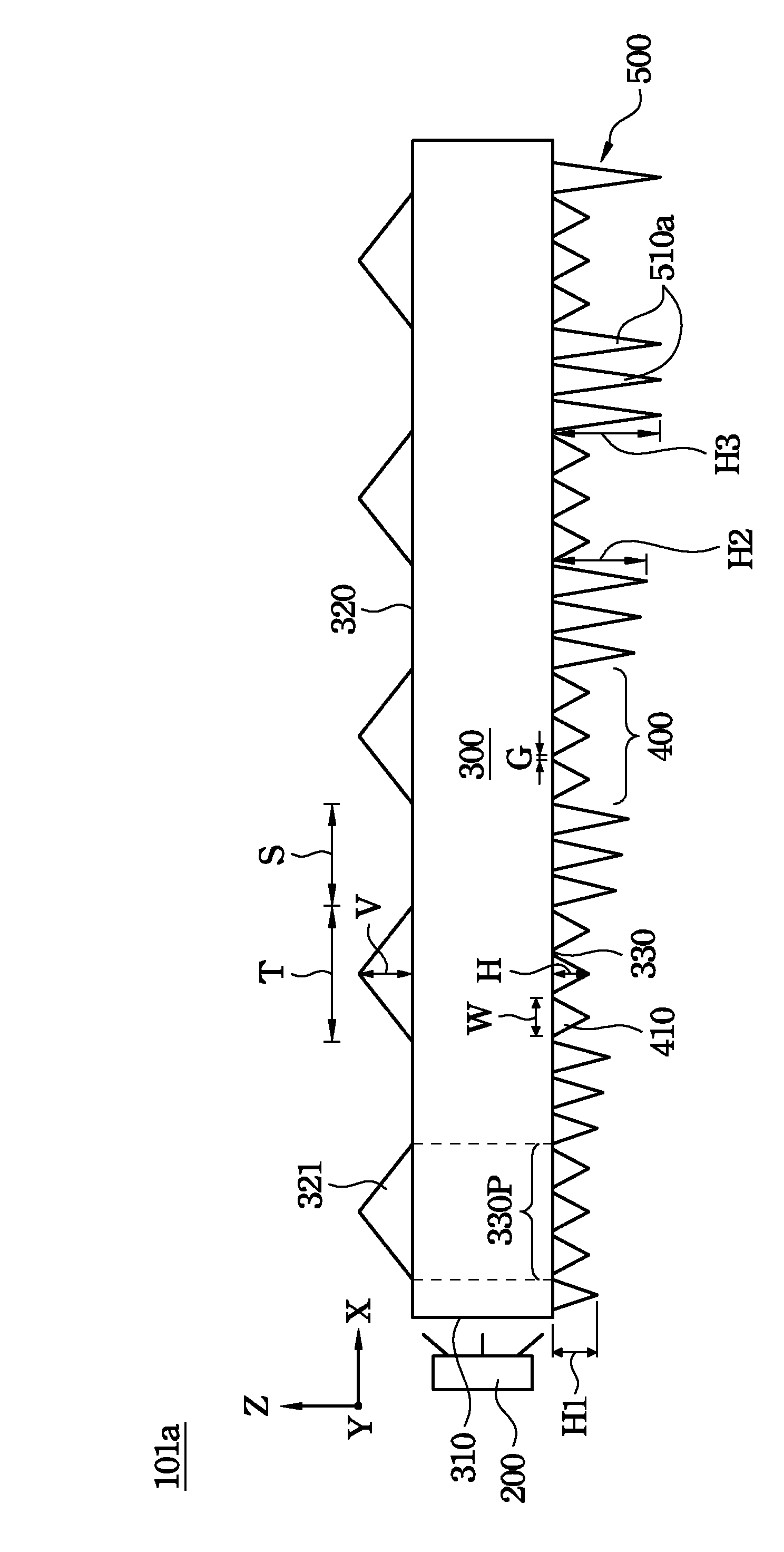
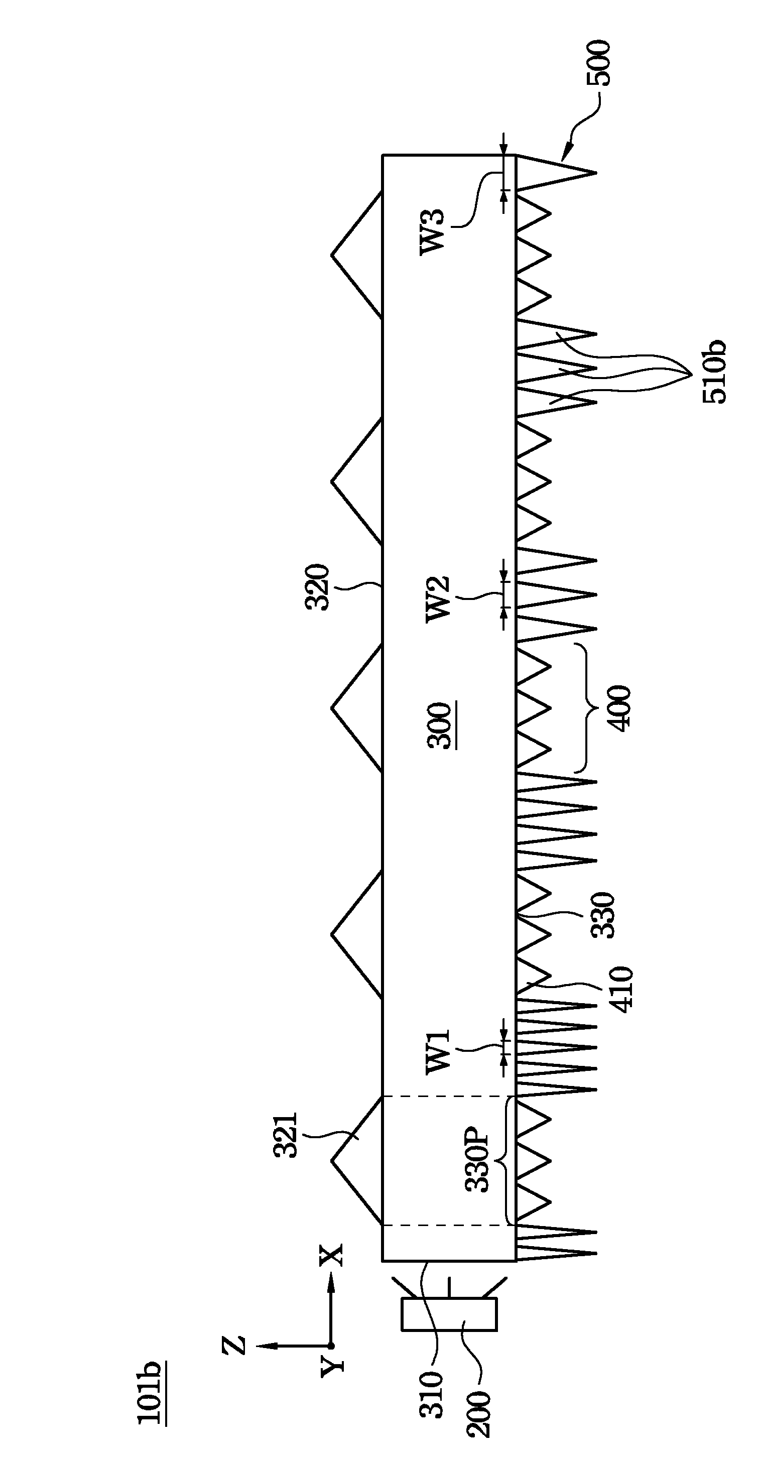
[0032] A light emitting module provided by the present invention includes a first light source and a light guide plate. The light guide plate includes a first light incident surface, a light exit surface, a reflection surface, a plurality of first three-dimensional unit groups and a second three-dimensional unit group. The first light source emits light toward the first light incident surface. The light-emitting surface includes a plurality of linear three-dimensional units arranged parallel to each other and spaced apart on the light-emitting surface. The reflective surface and the light-emitting surface are opposite to each other. The first light incident surface is located between the light exit surface and the reflective surface, and the first light incident surface is parallel to each linear three-dimensional unit. The first three-dimens...


PUM


Abstract

The invention relates to a luminescence module which comprises a light source and a light guiding plate, wherein the light source emits light towards one incident light surface of the light guiding plate; a plurality of linear three-dimensional units are configured on the emergent light surface of the light guiding plate; the reflecting surface of the light guiding plate comprises a plurality of first three-dimensional unit groups and second three-dimensional unit groups; the first three-dimensional unit groups are positioned on the vertical projection position of the reflecting surface corresponding to the linear three-dimensional units, and respectively comprise a plurality of first linear microstructures of the parallel linear three-dimensional units; the second three-dimensional unit groups are positioned in the area except the first three-dimensional unit groups on the reflecting surface and is composed of a plurality of second linear microstructures; the first linear microstructures and the second linear microstructures are different and are both parallel with the linear three-dimensional units and incident light surfaces; one of the perpendicular throw, maximum width and distribution density of the second linear microstructures is in proportion to the distance of the incident light surface and the second linear microstructures. The module can improve the unexpected linear bright fringes of the emergent light surface of the light guiding plate, thus homogenizing the emergent light luminance.

Description

technical field [0001] The invention relates to a light emitting module, in particular to a structure of the light emitting module. Background technique [0002] In the light-emitting module at the present stage, in the light guide plate system containing the microstructure patterns of linear grooves or ridges, a plurality of microstructure patterns of linear grooves or ridges are arranged at intervals on one side. When the light guide plate emits light, the position of the light-emitting surface corresponding to each linear groove or convex line will display multiple corresponding linear bright lines, resulting in uneven light emission on the light-emitting surface as a whole, and more optical cover sheets must be used to compensate , which consumes a lot of material cost and needs to be further improved. [0003] Therefore, if a light-emitting module design can be provided that can meet the above-mentioned requirements, or at least provide a solution to this defect, it wi...

Claims


Application Information

Patent Timeline
Patent Type & Authority Applications(China)
IPC IPC(8): F21S8/00F21V8/00
Inventor 叶钧皓
Owner SHANGHAI XIANGLONG ELECTRONICS TECH
Why Eureka
Try Eureka