
Light guide plate with uniform light emitting brightness

A light guide plate and brightness technology, which is applied in the field of light guide plates, can solve problems such as prominent heat dissipation, increased energy consumption, and weak astigmatism on the light-incoming side of the light guide plate, and achieves low power consumption, improved light output brightness, and uniform light output brightness Effect

Inactive Publication Date: 2014-10-08
东莞市现代精工实业有限公司
View PDF9 Cites 1 Cited by
  • Summary
  • Abstract
  • Description
  • Claims
  • Application Information

AI Technical Summary

Problems solved by technology

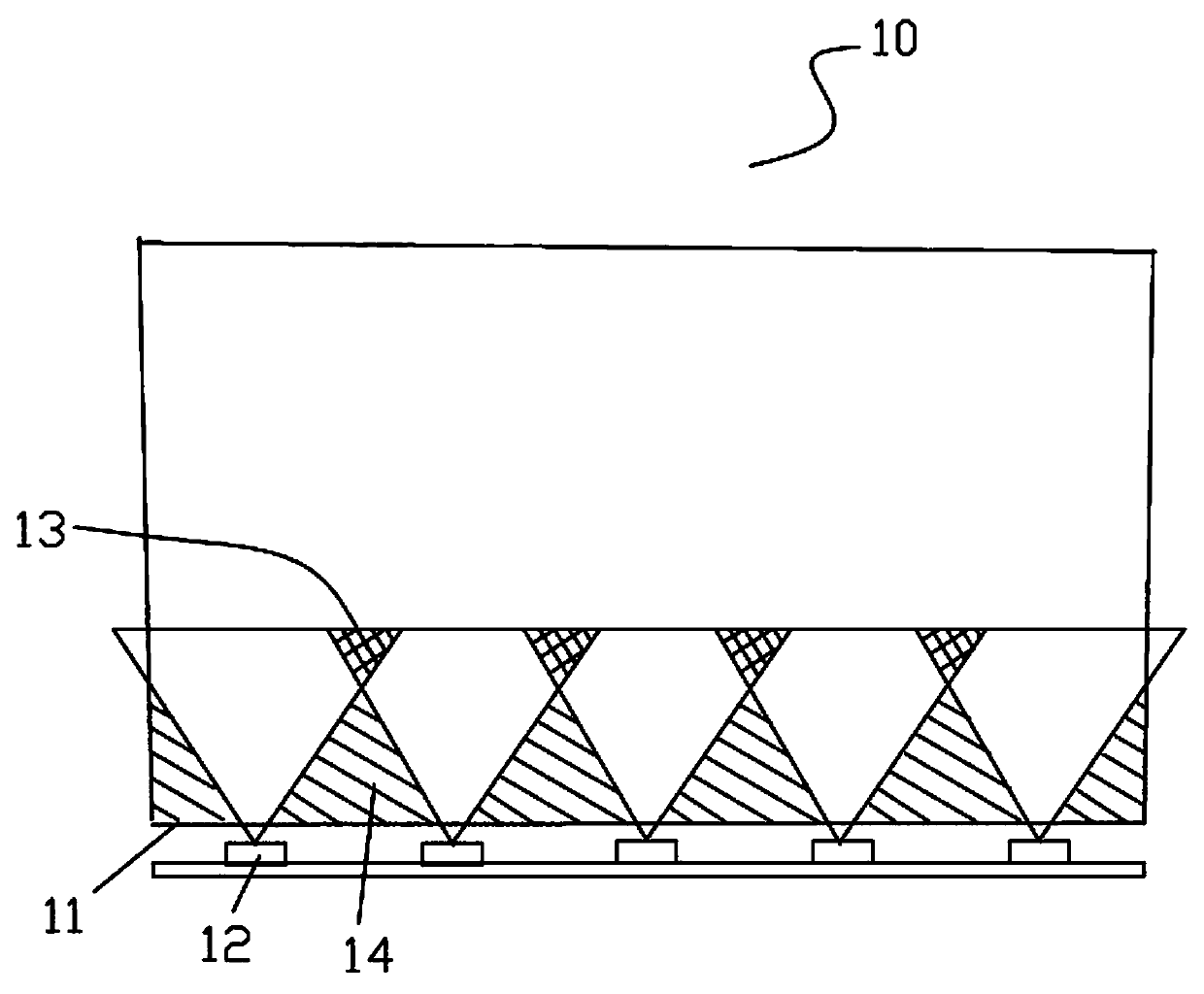
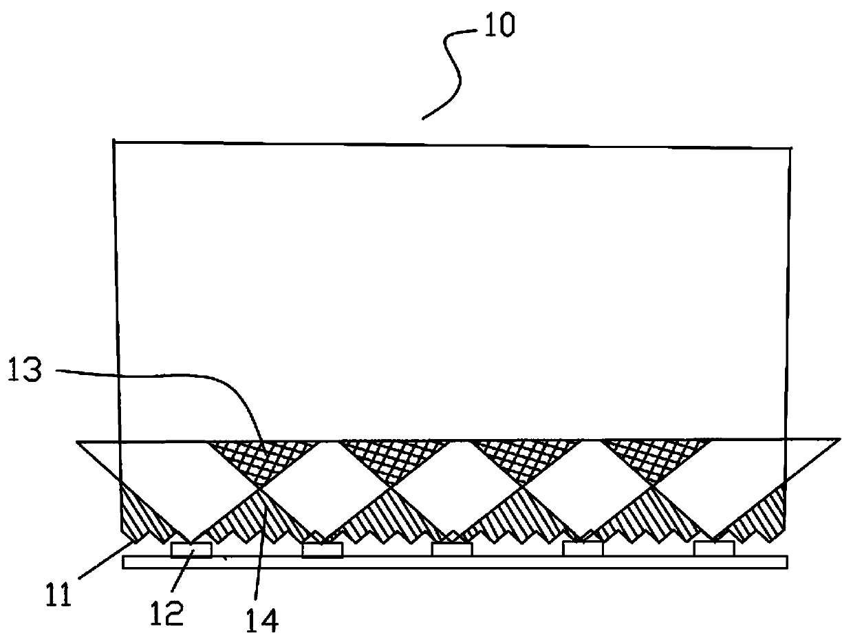
The front section, middle section and back section of this light guide plate have uniform light output brightness, especially the light output brightness of the rear section of the light guide plate will not be significantly weakened, but there are also shortcomings, that is, the astigmatism of the light incident side of the light guide plate is relatively weak, and the dark area is more obvious , it is necessary to increase the installation density of LED light sources, which will inevitably increase the bright spots on the light incident side, increase energy consumption, and prominent heat dissipation problems

Method used


Image

  • Light guide plate with uniform light emitting brightness
  • Light guide plate with uniform light emitting brightness
  • Light guide plate with uniform light emitting brightness

Examples


Embodiment Construction

[0030] The specific implementation manners of the present invention will be described below in conjunction with the accompanying drawings.

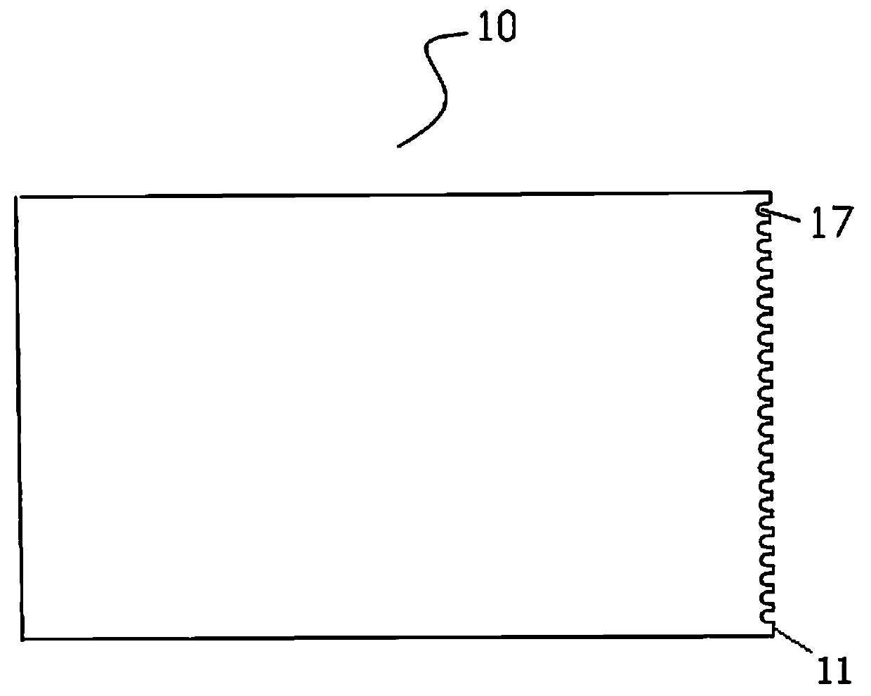
[0031] Such as Figure 5 to Figure 8 As shown, a light guide plate with uniform light output brightness includes a light output surface 15 and a light reflection surface oppositely arranged, and one of the common ends of the light output surface 15 and the light reflection surface is opposite to the light source, and the light of the light source is incident on the light guide plate. surface 11; the end face opposite to the light incident surface 11 is the rear end surface 16; on the light exit surface 15 extending from the light incident surface 11, there are many grooves 17 in the light guide plate, and the inside of the light guide plate is relatively far from the edge of the light guide plate. In other words, the length of the groove 17 extending from the light incident surface 11 into the light guide plate is 1 / 4 to 1 / 3 of the vertic...


PUM


Abstract

The invention discloses a light guide plate with uniform light emitting brightness, and relates to a light guide plate. The light guide plate comprises a light emitting surface and a reflection surface which are in opposite arrangement. The common end of the light emitting surface and the reflection surface is an incident surface which is opposite to a light source and is formed when light of the light source is incident on the light guide plate; the end surface opposite to the incident surface is a rear end surface; multiple grooves extend into the light guide plate from the incident surface and are prepared on the light emitting surface, relative to the edge of the light guide plate in the light guide plate, and the length of the grooves extending from the incident surface into the light guide plate is one quarter to one third of a vertical distance between the incident surface to the rear end surface; neighboring grooves are spaced at certain intervals. According to the invention, uniform brightness of the front segment, the middle segment and the rear segment of the light guide plate can be realized, and the brightness of the rear segment of the light guide plate in particular, can be improved by about 15%; and at the same time, the ark area at an incident side is quite small. Unification of excellent optical quality of the light guide plate, fewer light sources and less power consumption is realized. The light guide plate with the uniform light emitting brightness is suitable for large-dimension light guide plates.

Description

technical field [0001] The invention relates to a light guide plate, in particular to a light guide plate with uniform luminance. Background technique [0002] Backlight is one of the key components of display products, and TVs, computers, and mobile phones are all inseparable from the use of backlight. With the continuous improvement of the performance of display products, the requirements for backlight sources are getting higher and higher, such as light weight, thinner, low power consumption, high brightness, uniform light output, and low cost. The backlight is mainly composed of a light source and a light guide plate. The light guide plate is responsible for converting the light source into a surface light source with high brightness and uniform brightness. Therefore, the quality of the backlight source has a great influence on the quality of the light guide plate. With the same optical quality, low power consumption and low cost can be achieved. [0003] figure 1 It ...

Claims


Application Information

Patent Timeline
Patent Type & Authority Applications(China)
IPC IPC(8): G02B6/00F21V8/00
Inventor 顾钧
Owner 东莞市现代精工实业有限公司
Learn More