
Sealing Member

A technology for sealing components and components, which is applied to the sealing of engines, electrical components, telephone structures and other directions, can solve the problems of the sealing gasket 300 not being able to obtain sealing performance and the amount of compression is uneven, and achieve miniaturization and thin-walled, Good usability and stable sealing surface pressure effect

Inactive Publication Date: 2012-04-25
NIPPON MEKTRON LTD
View PDF9 Cites 6 Cited by
  • Summary
  • Abstract
  • Description
  • Claims
  • Application Information

AI Technical Summary

Problems solved by technology

[0015] However, since the amount of compression (gap) between the housings 100 and 200 is not uniform, there is a problem that the gasket 300 cannot obtain stable sealing performance.

Method used


Image

  • Sealing Member
  • Sealing Member
  • Sealing Member

Examples


Embodiment Construction

[0052] Hereinafter, the best mode for carrying out the present invention will be described.

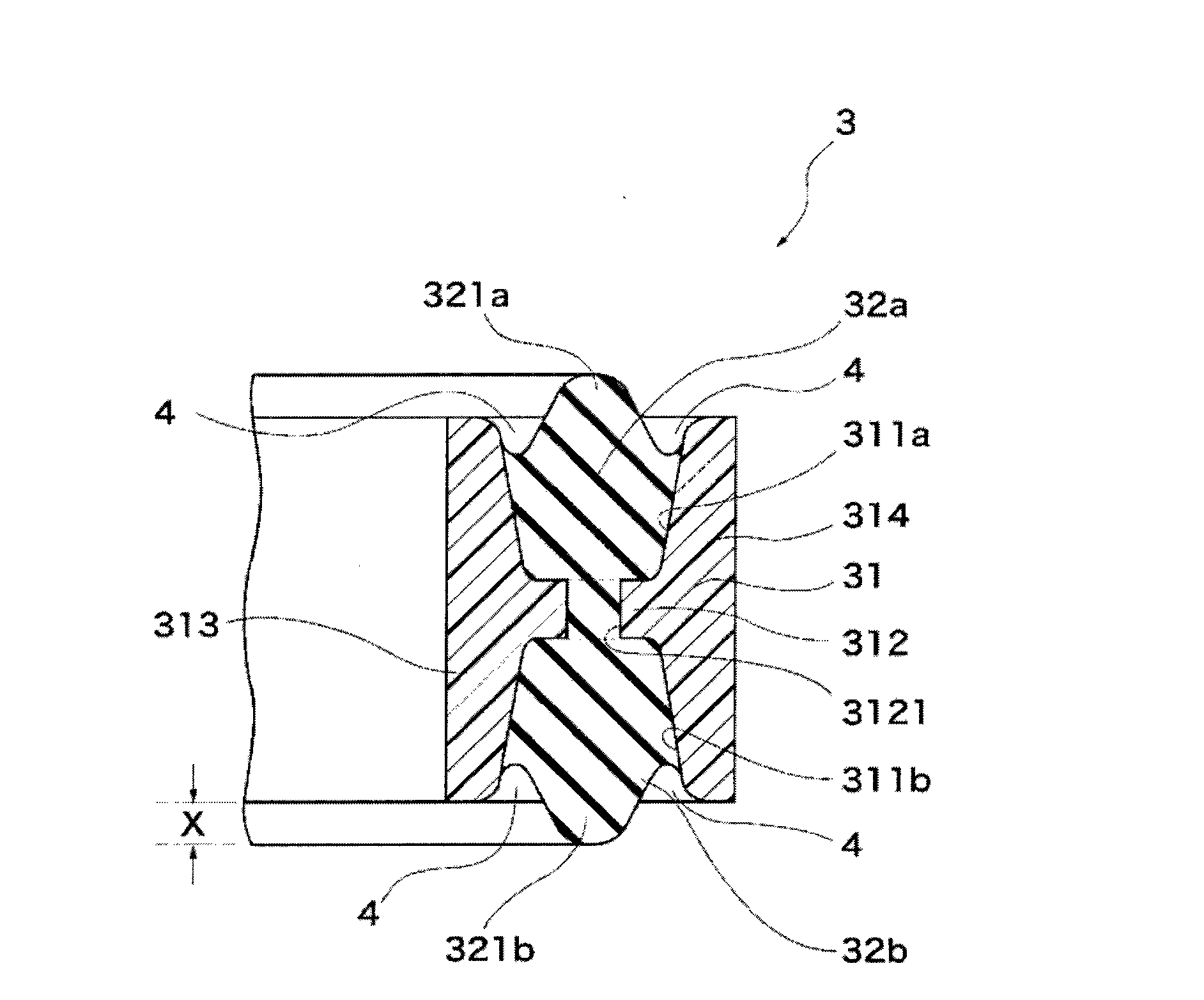
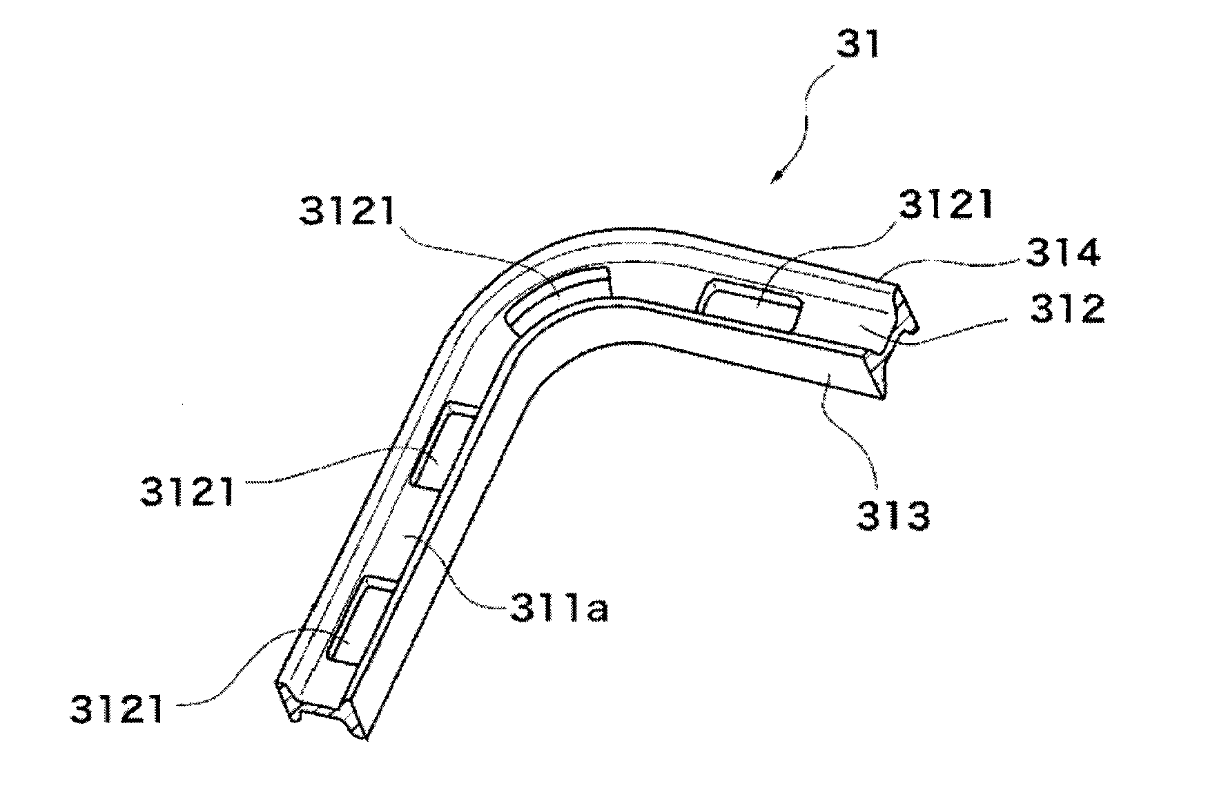
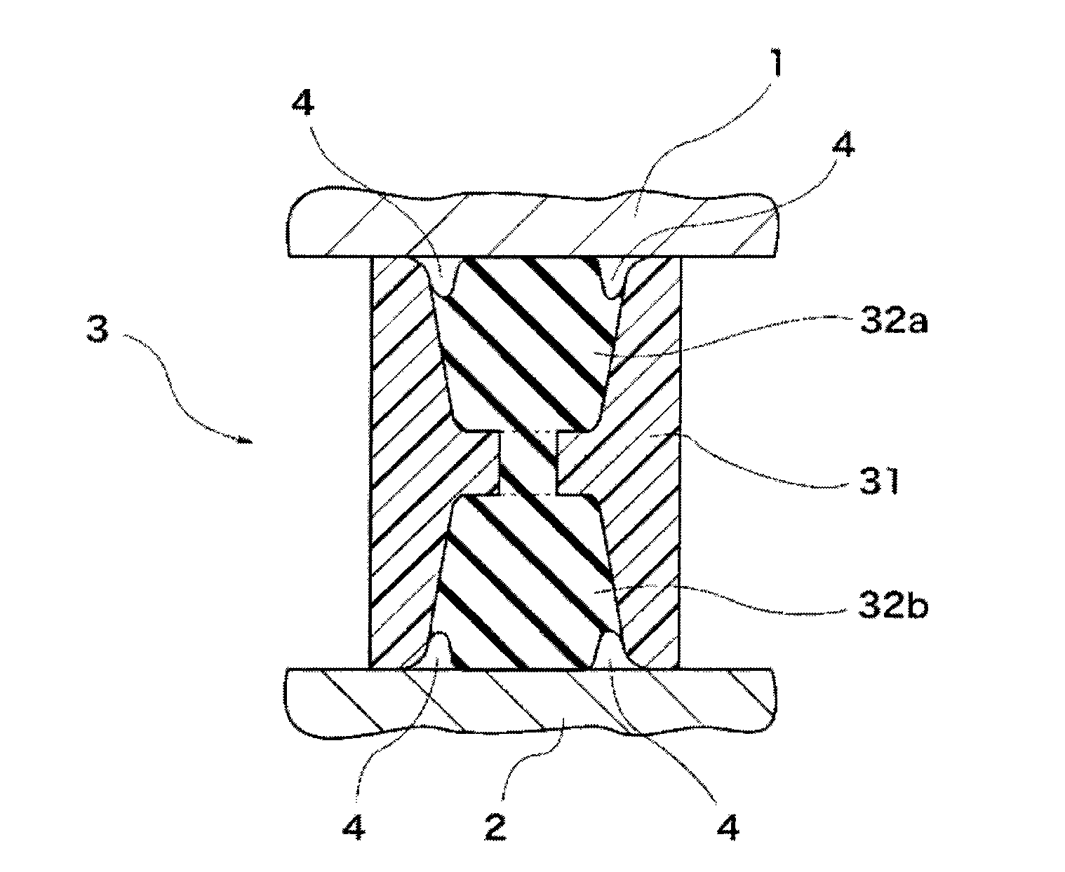
[0053] Such as Figure 1 to Figure 3 As shown, the sealing member involved in the present invention is a sealing member 3 located between one housing member 1 and another housing member 2 to seal the gap between the two members 1, 2, which is constituted as follows: The member 3 is composed of a holding member 31 made of a resin material having a substantially H-shaped cross section, and a pair of sealing members 32a and 32b made of a rubber material integrally provided on the two grooves 311a and 311b of the holding member 31. Lip portions 321a, 321b protruding from the two groove portions 311a, 311b are formed on the sealing members 32a, 32b.

[0054] In addition, if figure 2 As shown, the holding member 31 made of a resin material with a substantially H-shaped cross section is composed of an inner cylindrical portion 313, an outer cylindrical portion 314, and a connecting portio...


PUM


Abstract

Provided is a sealing member wherein it is not necessary to provide a groove in a housing and, accordingly, the size and the thickness of a case can be reduced; a gasket can be easily handled; and a stable sealing performance can be maintained. The sealing member is provided between a housing member and another housing member, and seals a gap between both housing members. The sealing member is comprised of a retainer member composed of a resin material and having a substantially H-shaped section, and a pair of rubber seal members integrally provided in both grooves of the retainer member. Lip portions projected from both grooves are formed on both rubber seal members.

Description

technical field [0001] The present invention relates to a sealing member of an electronic device, and more specifically, to a structure that seals such that water droplets do not enter the interior of electronic devices such as mobile phone terminals. [0002] Therefore, the sealing member of the present invention is most suitable as a sealing structure of waterproof electronic equipment. Background technique [0003] Such as Image 6 As shown, for example, in a mobile phone terminal, the housings 100 and 200 that fit together are combined to form a housing. In order to prevent water droplets from infiltrating the housing, an O-shaped rubber unit is installed between the housings 100 and 200. A gasket 300 made of a ring or the like (Patent Document 1). [0004] In addition, the packing 300 is disposed in an annular groove 600 provided in the housing 200 in order to keep the amount of compression (compression margin) constant. [0005] Thereby, when the housings 100 and 200...

Claims


Application Information

Patent Timeline
Patent Type & Authority Applications(China)
IPC IPC(8): F16J15/10F16J15/06H04M1/02
CPCH05K5/061F16J15/127F16J15/104H04M1/0249H04M1/18F16J15/06F16J15/10H04M1/02
Inventor 新村直哉林隆浩高冈伸
Owner NIPPON MEKTRON LTD
Learn More