Tennis ball feed and swing speed monitoring device

A speed monitoring and ball supplying technology, which is applied in the direction of sports accessories, etc., can solve the problems of inability to accurately monitor the player's swing speed, difficulty for the batter to accurately select the hitting point, and low regularity of the ball supply

Inactive Publication Date: 2014-03-12
HARBIN NORMAL UNIVERSITY
View PDF5 Cites 0 Cited by
  • Summary
  • Abstract
  • Description
  • Claims
  • Application Information

AI Technical Summary

Problems solved by technology

[0004] The purpose of the present invention is to solve the problems of the low ball supply regularity of the existing artificial tennis ball supply method, the difficulty for the hitter to accurately select the hitting point, and the inability to accurately monitor the swing speed of the player when the ball is touched, thereby providing A tennis ball supply and swing speed monitoring device

Method used


Image

  • Tennis ball feed and swing speed monitoring device
  • Tennis ball feed and swing speed monitoring device
  • Tennis ball feed and swing speed monitoring device

Examples


specific Embodiment approach 1

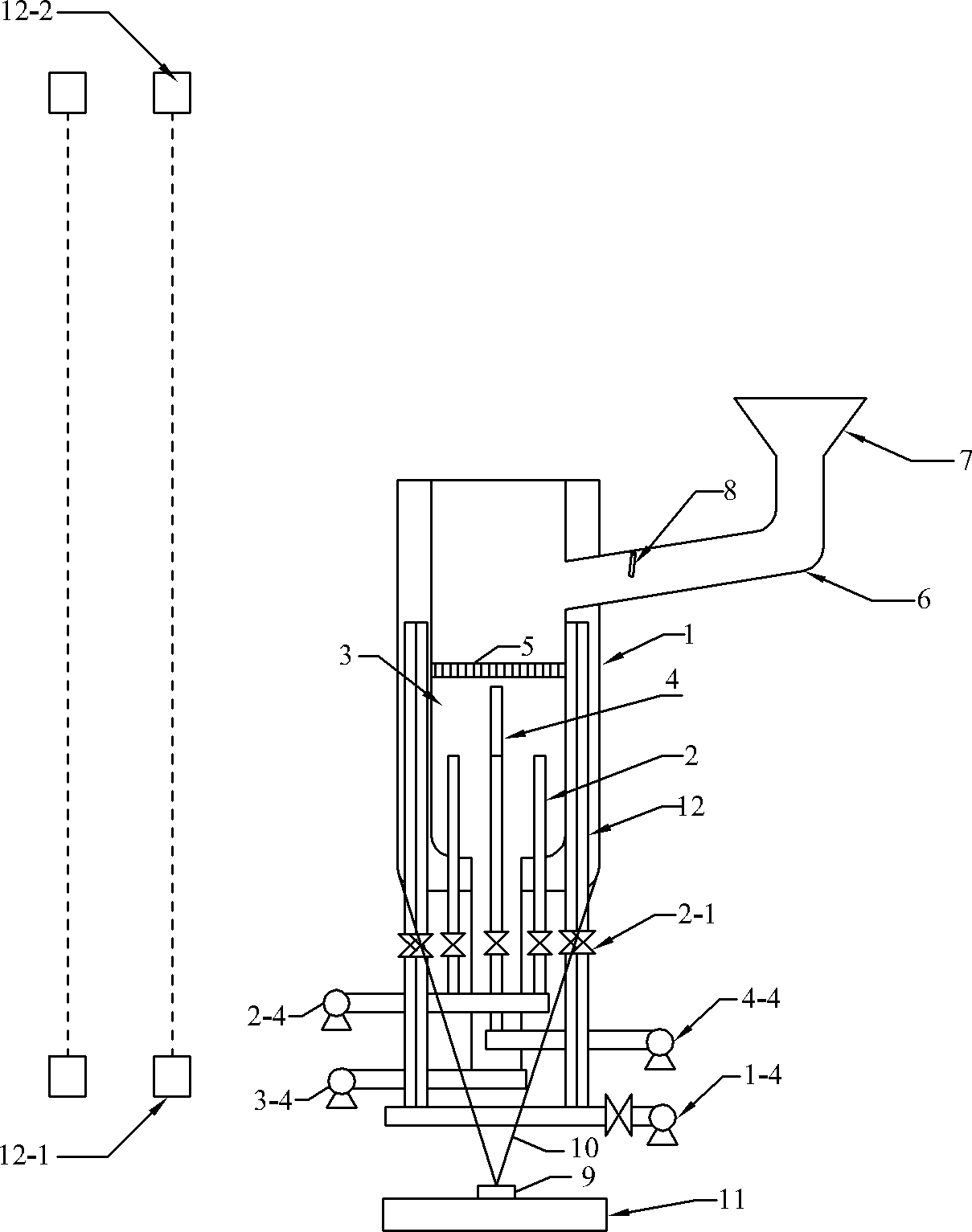
[0024] Specific implementation mode 1. Combination Figures 1 to 3 Illustrate this specific embodiment, tennis ball supply and swing speed monitoring device, it comprises outer cylinder 1, No. 4. Rectifier grid 5, ball supply pipeline 6, ball collecting box 7, baffle plate 8, N groups of beam transceiver devices and control system;

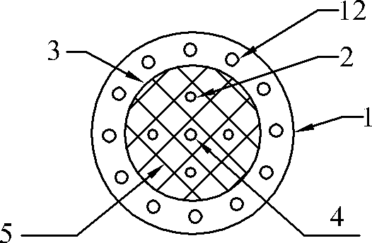
[0025] The outer cylinder 1 and the air supply pipeline 3 for suspension are coaxially sleeved together, and the outer cylinder 1 is located on the outside; the air inlet on the side of the outer cylinder 1 communicates with the air outlet of the No. 1 air pump 1-4; the air supply pipeline 3 for suspension is located The air inlet at the lower part communicates with the air outlet of No. 3 air pump 3-4; the rectifying grid 5 is fixed on the inner wall of the air supply pipeline 3 for suspension;

[0026] L root limit air supply pipelines 12 are evenly distributed in the annular space between the outer cylinder 1 and the suspension air supply pipe...

specific Embodiment approach 2

[0038] Embodiment 2. The difference between this embodiment and the tennis ball and swing speed monitoring device described in Embodiment 1 is that it also includes an air supply pipeline 4 and a high-pressure air pump 4-4 for injection; an air supply pipe for injection Road 4 is coaxially sleeved inside the air supply pipeline 3 for suspension; the air inlet at the lower part of the air supply pipeline 4 for injection is connected with the air outlet of the high-pressure air pump 4-4, and the upper part of the air supply pipeline 4 for injection is located at the lower side of the rectifying grid 5;

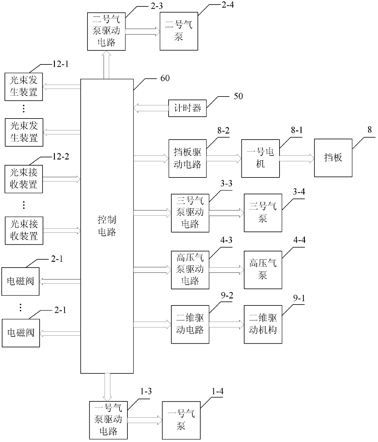
[0039] The control system also includes a high-pressure air pump drive circuit 4-3; the high-pressure air pump drive signal output end of the control circuit 60 is connected to the air pump drive signal input end of the high-pressure air pump drive circuit 4-3; the drive signal output end of the high-pressure air pump drive circuit 4-3 Connect with the drive signal input end of the...

specific Embodiment approach 3

[0041] Embodiment three. The difference between this embodiment and the tennis ball and swing speed monitoring device described in embodiment two is that it also includes M air supply pipelines 2 for rotation, M solenoid valves 2-1 and No. 2 air pump 2-4, the M rotation air supply pipelines 2 are uniformly distributed in the suspension air supply pipeline 3 centered on the central axis of the outer cylinder 1, and the M rotation air supply pipelines 2 are parallel to each other On the central axis of the outer cylinder 1, the air inlets at the bottom of each rotating air supply line 2 are respectively connected to the air inlets of a solenoid valve 2-1, and the air outlets of all the solenoid valves 2-1 are connected to the second air pump 2 at the same time. The air outlet of -4 is connected;

[0042] The control system also includes No. two air pump driving circuit 2-3, the No. two air pump driving signal output end of the control circuit 60 is connected with the air pump dr...


PUM


Abstract

The invention discloses a tennis ball feed and swing speed monitoring device, and relates to a ball feed and swing speed monitoring device. The device aims to solve the problems that a batter hardly selects a hitting point accurately, and swing speed of a player touching a ball cannot be monitored accurately due to low ball feed regularity in the conventional manual tennis ball feed mode. Suspension ball feed is adopted, and the player can accurately select the hitting point for shooting training; launching tennis ball feed can be performed, a ball feed angle can be arbitrarily selected, and the tennis ball movement track can reappear, so the player can effectively do catching training; and the swing speed of the player can be monitored in a light beam cutting mode. The device is suitable for a tennis ball training process.

Description

technical field [0001] The invention relates to a ball feeding and swing speed monitoring device. Background technique [0002] At present, in the tennis batting training, the batting training methods adopted mainly include two kinds of batting training methods: training with others and using a server to supply the ball. The former method of supplying the ball is greatly affected by human factors, and the regularity of the supply Low; while using the ball machine to supply the ball, the speed of the ball machine is faster, and it is difficult for the hitter (especially beginners) to accurately select the hitting point; moreover, it is currently impossible to accurately monitor the swing speed of the player when he touches the ball; [0003] Utilize athlete's movement information to monitor the tennis ball and the swing speed monitoring device that monitors the athlete's action technical process, has not yet appeared at home and abroad. Contents of the invention [0004] T...

Claims


Application Information

Patent Timeline
Patent Type & Authority Patents(China)
IPC IPC(8): A63B71/06A63B69/40A63B69/38
Inventor 夏国滨孙长明徐福水张军侯政志
Owner HARBIN NORMAL UNIVERSITY
Why Eureka
Try Eureka