Supercharge Your Innovation With Domain-Expert AI Agents!

Elevator system

An elevator system and elevator car technology, applied in elevators, transportation and packaging, etc., can solve the problems of insufficient charging of energy storage devices, cut peak power, etc., and achieve the effect of saving energy and increasing the possibility of charging

Inactive Publication Date: 2015-05-20
HITACHI LTD
View PDF9 Cites 0 Cited by
  • Summary
  • Abstract
  • Description
  • Claims
  • Application Information

AI Technical Summary

Problems solved by technology

In the elevators described in Patent Document 2 to Patent Document 4, when the AC power supply is cut off at the time of entering the standby state, the peak power cannot be reduced when the elevator is started next time due to insufficient charging of the energy storage device.

Method used


Image

  • Elevator system
  • Elevator system
  • Elevator system

Examples


no. 1 example

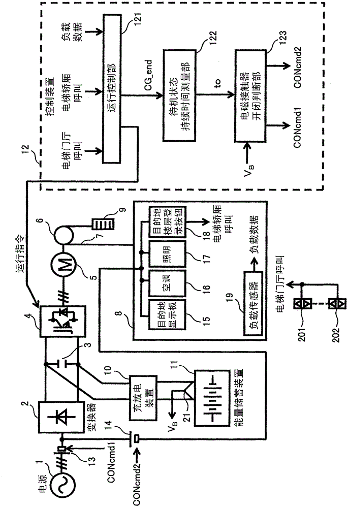
[0036] figure 1 A configuration diagram showing an elevator system according to a first embodiment of the present invention. figure 1 The elevator system is a "peak power reduction type elevator system" that charges an energy storage device with regenerative power and power supply power, and cuts the peak power of the power supply during power operation. By reducing the peak power, it is possible to reduce the electricity bill paid to the electric power company, and on the other hand, by recycling the regenerative power, it is possible to reduce the amount of electric power from the power source used for driving the elevator, thereby saving energy.

[0037] First, the basic configuration of the elevator driving unit in the elevator system of the present invention will be described. Three-phase AC power from an AC power source 1 that is a commercial power source is converted into DC power by an inverter 2 including, for example, a diode rectifier. The DC power converted by th...

no. 2 example

[0052] Figure 5 is a block diagram of an elevator system according to a second embodiment of the present invention. The connection points of the AC power supply 1 and the equipment in the elevator car, namely, the destination display board 15, the air conditioner 16, the lighting 17 and the destination floor registration button 18 of this embodiment are different from those of the first embodiment. Hereinafter, in this embodiment, refer to Figure 5 Only the parts different from the first embodiment will be described.

[0053] The equipment in the elevator car (destination display board 15 , air conditioner 16 , lighting 17 and destination floor registration button 18 ) is connected to a node between AC power supply 1 and electromagnetic contactor 13 via electromagnetic contactor 14 . The difference between this embodiment and the first embodiment is that this embodiment does not pass through the electromagnetic contactor 13 when supplying power to the equipment in the elev...

no. 3 example

[0057] Figure 6 is a block diagram of an elevator system according to a third embodiment of the present invention. The method of supplying power to the equipment in the elevator car, that is, the destination display panel 15, the air conditioner 16, the lighting 17, and the destination floor registration button 18 of this embodiment is different from that of the first embodiment. Therefore, in this example, refer to Figure 6 , only the parts different from the first embodiment will be described.

[0058]For example, an inverter 22 such as a PWM inverter is connected to both ends of the DC circuit (smoothing capacitor 3) of the elevator drive unit, and the DC voltage is converted into single-phase AC power of a predetermined frequency and voltage by the inverter 22 . The inverter 22 is connected to the equipment in the elevator car 8 (destination display panel 15, air conditioner 16, lighting 17 and destination floor registration button 18) via the electromagnetic contacto...


PUM


Abstract

PROBLEM TO BE SOLVED: To solve such the problem that in an elevator system of a peak power cut system, energy for discharging peak power portion has to be normally charged in an energy accumulation device, and in the peak power cut system, when the energy accumulation device is in an insufficient charge state, power has to be supplied from a power source even when a standby state continues for a certain time, though conventionally, when the standby state continues for a certain time, the power source is cut off. SOLUTION: An electromagnetic contactor is provided between a commercial power source and a converter. The electromagnetic contactor is released when the elapsed time exceeds a given time after an elevator has become a standby state, and when the charge capacity of the energy accumulation device exceeds a target value. COPYRIGHT: (C)2012,JPO&INPIT

Description

technical field [0001] The present invention relates to an elevator system, and more particularly to an elevator system that uses an energy storage device such as a storage battery to release energy equivalent to peak power from the energy storage device to reduce the peak power of a power supply. Background technique [0002] The characteristic of the elevator is that the use of the elevator is usually concentrated during a certain period of time such as working time, lunch time and off-duty time, while at other times, there are fewer users and the standby state is longer. Therefore, by reducing the standby power consumed by the elevator in the standby state, it is possible to effectively achieve further energy saving of the elevator. [0003] As a method of reducing standby power, the following proposals have been proposed. In Patent Document 1, a switch for the standby state is provided in the elevator lobby, and when the end user of the elevator operates the switch, the...

Claims


Application Information

Patent Timeline
Patent Type & Authority Patents(China)
IPC IPC(8): B66B1/34
Inventor 村冈一史吉川敏文绫野秀树大贯朗古桥昌也深田裕纪岸川孝生
Owner HITACHI LTD
Features
  • R&D
  • Intellectual Property
  • Life Sciences
  • Materials
  • Tech Scout
  • Unparalleled Data Quality
  • Higher Quality Content
  • 60% Fewer Hallucinations
Learn More