Burner for ranges

A burner, burner head technology, applied in burners, burners, burner safety devices, etc., can solve the problems of increased cost and time required for cutting, and achieves prevention of tempering, good fire mobility, and cost reduction Effect

Active Publication Date: 2012-05-02
RINNAI CORP
View PDF4 Cites 3 Cited by
  • Summary
  • Abstract
  • Description
  • Claims
  • Application Information

AI Technical Summary

Problems solved by technology

However, in this method, the cutting process takes time, resulting in an increase in cost

Method used


Image

  • Burner for ranges
  • Burner for ranges
  • Burner for ranges

Examples


Embodiment Construction

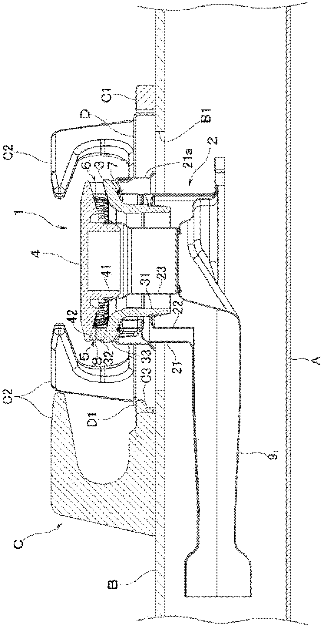
[0036] refer to figure 1 , A is the main body of the stove, B is the top plate covering the upper surface of the main body A of the stove, and the burner opening B1 opened on the top plate B is provided close to the burner 1 for the stove. Moreover, the flame stay C is mounted on the top board B so that the opening B1 for burners may be surrounded. And, the cooking vessel mounted on the fire stand C is heated by the burner 1 . In addition, the fire prop C includes a ring-shaped fire prop frame C1 and a plurality of fire prop claws C2 radially installed on the fire prop frame C1.

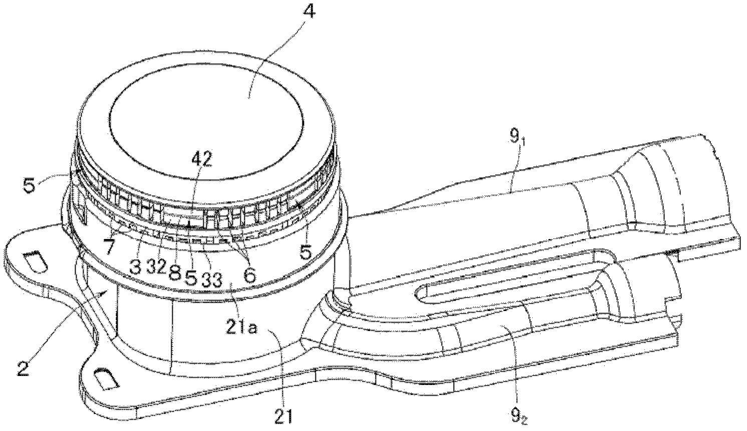
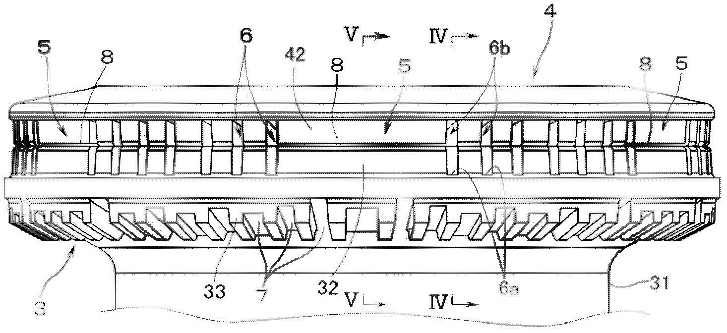
[0037] The burner 1 includes: a sheet metal burner body 2 inserted through the burner opening B1; a burner head 3 provided on the burner body 2 and made of a metal casting or forging such as brass; And the burner cover 4 provided on the burner head 3 is made of a metal casting or forging such as brass. Such as figure 2 As shown, in the peripheral portion between the burner head 3 and the burner ...


PUM


Abstract

The invention provides a burner for ranges, wherein the outer peripheral portion between a burner head (3) composed of a casting piece or a forging piece and a burner cover (4), and the aligning part of a fire chaplet (5) positioned in the same direction with a fire chaplet claw, are formed with an elongated slit flame port (6) in the up-and-down direction. Therefore, an elongated slit flame port of a sufficient length in the up-and-down direction can be formed without the need of casting or cutting machining after the forging process, while the flame is good in mobility. The head annular sidewall (32) raised on the outer peripheral part of the upper surface of the burner head is provided with a flame port groove (6a) at the lower part of the elongated slit flame port during the casting or forging forming process. The cover annular wall (42) vertically arranged on the outer peripheral part of the lower surface of the burner cover is provided with a flame port groove (6b) at the upper part of the elongated slit flame port during the casting or forging forming process. The aligned part of the fire chaplet, a moving fire flame port (8) is formed between the end face of the head annular wall and the end face of the cover annular wall.

Description

technical field [0001] The present invention relates to a burner for a stove provided in a stove. More specifically, it relates to a burner for a stove, which comprises: a burner body to which a mixture of fuel gas and primary air is supplied; a burner head , consisting of castings or forgings provided on the burner body; and the burner cover, consisting of castings or forgings provided on the burner head. Background technique [0002] Conventionally, as a burner for a stove, there is known a structure in which a burner cover is made of sheet metal, and on its outer peripheral surface, it is positioned between a plurality of fire spreader claws of a fire spreader placed on a stove top plate. A vertically elongated slit flame opening from which a mixed gas is ejected is formed between aligned portions of a plurality of flame stays in the same orientation (for example, refer to Patent Document 1). Here, if the flame port is formed as a slit flame port, it is possible to preve...

Claims


Application Information

Patent Timeline
Patent Type & Authority Applications(China)
IPC IPC(8): F23D14/02F23D14/46
CPCF23D14/06F23D14/58F23D14/72F23D2209/00F24C3/027F24C3/085
Inventor 佐藤裕康冈本英男竹本安伸
Owner RINNAI CORP
Why Eureka
Try Eureka