
High-precision coder

A technology of high-precision encoders and coding wheels, which is applied in the direction of instruments, conversion sensor output, measuring devices, etc., can solve the problem that it cannot be lower than a certain value, and achieve the effect of improving the physical resolution

Active Publication Date: 2014-03-19
CHENGDU EBRIDGE TECH
View PDF4 Cites 2 Cited by
  • Summary
  • Abstract
  • Description
  • Claims
  • Application Information

AI Technical Summary

Problems solved by technology

Since the birth of the disc encoder, the method of setting the code bar on the side of the code disc has been used. Due to the limitation of the radius of the code disc, the inner and outer radii of the code bar set on the side of the code disc must be smaller than the diameter of the code disc, so its The equivalent radius of the midpoint of the inner and outer radii must be smaller than the radius of the code disc, which limits the number of code bars that can actually be set in the case of sensors with the same resolution; because the code bar of the traditional disc encoder is set on the side of the code disc, its code bar The distance between the code bar and the code bar is fan-shaped, limited by the ability of the photoelectric sensor, the difference between the inner and outer radius of the fan cannot be lower than a certain value, so the photoelectric type is greatly restricted on the small-diameter encoder, generally the diameter is smaller Small encoders can only use magnetoelectric, but magnetoelectric is much worse than photoelectric in terms of temperature adaptability and anti-electromagnetic interference

Method used


Image

  • High-precision coder
  • High-precision coder
  • High-precision coder

Examples


Embodiment 1

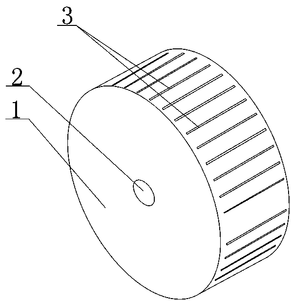
[0023] Such as Figures 1 to 3 As shown, the high-precision code wheel of the present invention includes a code wheel 1. The code wheel 1 is cylindrical, has two disc surfaces and a wheel surface connected between the disc surfaces, and is provided with a code wheel along the center of the disc. The through hole 2 of the axis is provided with as many code bars 3 as possible on the wheel surface. The code bars 3 are in a regular rectangle, and the code bars 3 are parallel to each other. For the wheel surface of the photoelectric encoder code wheel 1, there are Two surface treatment methods: the first one is to use chrome plating, gold plating or silver plating to treat the surface into a bright reflective surface; the second one is to use black matte treatment to form a low reflective surface; The code bar 3 is engraved on the wheel surface of the code wheel 1, and the engraving on the bright reflective surface appears as low-reflection stripes, and the engraving on the low-ref...

Embodiment 2

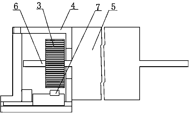
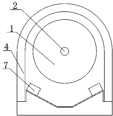
[0025] Such as Figures 4 to 5As shown, the high-precision encoder of the present invention includes a code wheel 1. The code wheel 1 is cylindrical and has two disc surfaces and a wheel surface connected between the disc surfaces. The through hole 2 of the axis is provided with a plurality of code strip rings containing as many code strips 3 as possible on the wheel surface. The code strips 3 are in a regular rectangle, and the code strips 3 are parallel to each other. Any two adjacent code strips The code bar 3 corresponding to the position on the ring is connected as a whole, the distance between the code bar 3 on a single code bar ring is the same, but the distance between the code bar 3 on different code bar rings is not the same, and press from left to The order of the right gradually shrinks. There are two surface treatment methods for the wheel surface of the photoelectric encoder code wheel 1 after polishing: the first method is to use chrome plating, gold plating or...


PUM


Abstract

A high-precision coding wheel and a coder formed thereby, including a code wheel (1). The code wheel (1) is of cylindrical shape, with a through-hole (2) for inserting a rotation shaft (6) being provided on the cylinder axis thereof. The wheel surface of the code wheel (1) is provided with code strips (3) as much as possible, and each code strip (3) is parallel to the axis of the code wheel (1). By replacing a code disc with a coding wheel and providing code strips (3) on the wheel surface of the coding wheel, in the situation where the diameter is the same and the widths of the code strips (3) are the same, the number of the code strips (3) provided on the wheel surface of the code wheel (1) is far more than that of the code strips provided on a conventional code disc, which utilizes the radius of the code wheel (1) to the greatest extent, and therefore, the number of code strips which can be provided is maximized, improving the physical resolution of the coder with the same diameter to the greatest extent. In addition, by providing code strips(3) on the wheel surface of the code wheel (1) and by virtue of the code strip (3) being in the shape of a standard rectangle, the present invention can be well suited to small-diameter photoelectric coders.

Description

technical field [0001] The invention relates to a small-volume and high-precision encoder, in particular to a high-precision encoder wheel and the encoder formed therefrom. Background technique [0002] An encoder is a device that compiles and converts signals or data into signal forms that can be used for communication, transmission and storage. The encoder converts the angular displacement or the linear displacement into an electrical signal, the former becomes a code disc, and the latter is called a yardstick. According to the readout method, the encoder can be divided into two types: contact type and non-contact type. The contact type adopts the brush output, and the brush touches the conductive area or the insulating area to indicate whether the state of the code is "1" or "0"; the non-contact type accepts the sensitive element is a photosensitive element or a magnetic sensitive element, and when the photosensitive element is used, the transmission type The state of t...

Claims


Application Information

Patent Timeline
Patent Type & Authority Patents(China)
IPC IPC(8): G01D5/347
CPCG01D5/2451G01D5/347
Inventor 吕力
Owner CHENGDU EBRIDGE TECH
Learn More