
A Vector Array Discrimination Method Based on Sound Pressure and Vibration Velocity Cross Spectrum Method

A cross-spectral method and vector array technology, applied in the research field of underwater acoustic direction finding, can solve the problems of low resolution accuracy of port and starboard of vector array, uneven resolution of port and starboard, etc.

Active Publication Date: 2018-07-24
HARBIN ENG UNIV
View PDF3 Cites 0 Cited by
  • Summary
  • Abstract
  • Description
  • Claims
  • Application Information

AI Technical Summary

Problems solved by technology

[0019] The purpose of the present invention is to propose a vector array starboard and starboard resolution method based on the sound pressure and vibration velocity cross-spectrum method to solve the problem that the starboard and starboard sides of the vector array have low resolution accuracy and the problem of uneven resolution of the starboard and starboard sides within the 360-degree range.

Method used


Image

  • A Vector Array Discrimination Method Based on Sound Pressure and Vibration Velocity Cross Spectrum Method
  • A Vector Array Discrimination Method Based on Sound Pressure and Vibration Velocity Cross Spectrum Method
  • A Vector Array Discrimination Method Based on Sound Pressure and Vibration Velocity Cross Spectrum Method

Examples


specific Embodiment approach 1

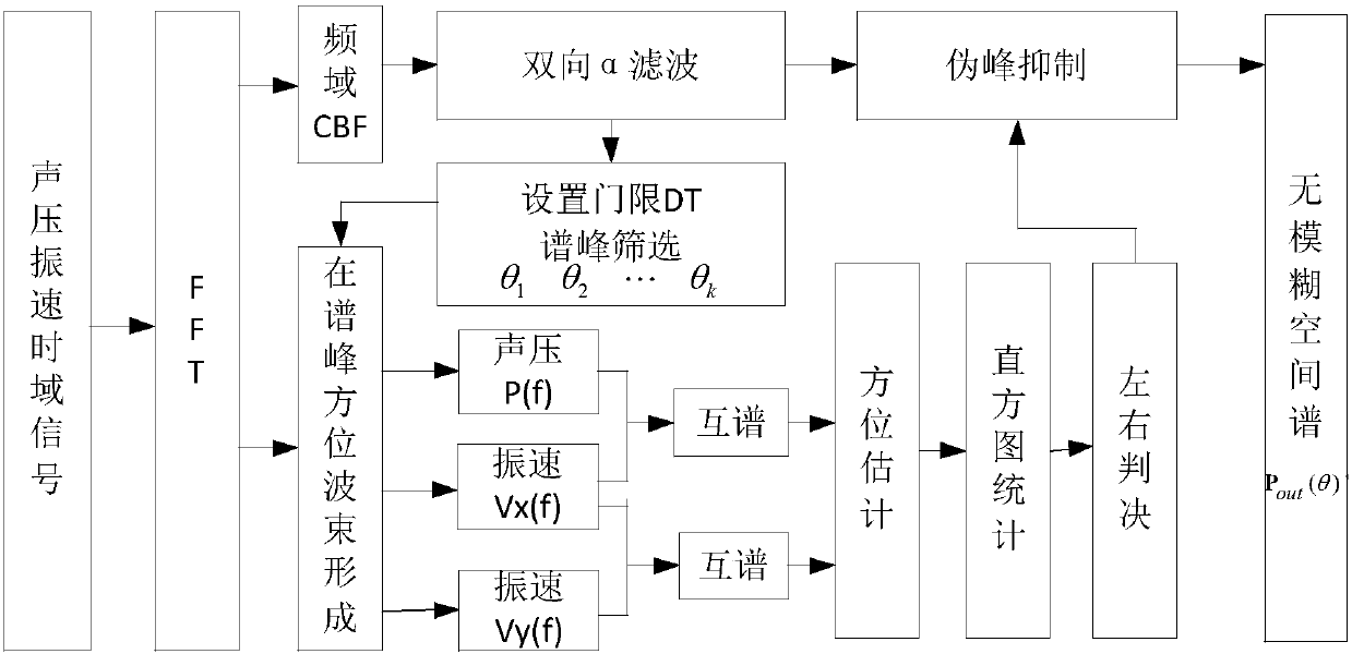
[0087] A kind of vector array starboard and starboard discrimination method based on sound pressure and vibration velocity cross-spectrum method in this embodiment, combined with figure 2 and image 3 As shown, the method is realized through the following steps:

[0088] Step 1. After the sound pressure signal received by the multi-element array is converted into a frequency domain signal, the frequency domain broadband conventional beamforming process is performed to obtain the original spatial spectrum matrix P out (θ); wherein, the spatial spectrum matrix refers to the matrix of the output spatial spectrum type;

[0089] Step 2. For the original spatial spectrum matrix P obtained in step 1 out (θ) performs bidirectional first-order recursive filtering to obtain the smoothed spatial spectrum P α (θ);

[0090] Step 3. According to the smooth spatial spectrum P obtained in step 2 α (θ), in the smooth space spectrum P α (θ) on the basis of improving D T decibels to obta...

specific Embodiment approach 2

[0097] The difference from Embodiment 1 is that in this embodiment, based on the sound pressure and vibration velocity cross-spectrum method of the vector array left and right sides, the frequency-domain broadband conventional beamforming is performed on the sound pressure signal received by the multi-element array as described in step 1. (CBF) processing to obtain the original spatial spectrum matrix P out The process of (θ) is,

[0098] Step 11, performing fast Fourier transform (abbreviated as FFT) to the received sound pressure and vibration velocity time domain signals into frequency domain signals;

[0099] Step 12: Perform conventional beamforming (referred to as CBF) processing on each frequency point signal in the frequency domain signal working frequency band bandwidth within the B range, obtain the spatial spectrum of each frequency point, and output; and express the spatial spectrum as P( f i ,θ), and

[0100] P(f i ,θ)=a(f i ,θ) H R(f i )a(f i ,θ); where, ...

specific Embodiment approach 3

[0106] The difference from the specific embodiment 1 or 2 is that in this embodiment, a vector array based on sound pressure and vibration velocity cross-spectrum method for distinguishing left and right sides, the original spatial spectrum matrix P obtained in step 1 is described in step 2. out (θ) performs bidirectional first-order recursive filtering to obtain the smoothed spatial spectrum P α The process of (θ) is,

[0107] Step 21, using a two-way first-order recursive filter, that is, the α filter is used to filter the original spatial spectrum matrix P out (θ) for smoothing and filtering; at the same time extract the original spatial spectrum matrix P out (θ) peak;

[0108] Step 22. The original spatial spectrum matrix P out (θ) performs two-way α filtering to get P α (θ), according to the adjustability of the filter coefficient, the filter coefficient is adjusted to be smaller, so that the filtering effect is more obvious, and the obtained P α(θ) is also flatter. ...


PUM


Abstract

The invention belongs to the underwater sound direction-finding field and relates to a sound pressure and vibration velocity cross-spectrum method-based vector array port and starboard discrimination method. The method includes the following steps that: step (1) after received sound pressure signals are converted into frequency-domain signals, frequency-domain broadband conventional beamforming processing is carried out on the frequency-domain signals, so that an original spatial spectrum matrix can be obtained, wherein the spatial spectrum matrix is a matrix of an outputted spatial spectrum type; step (2) bidirectional one-order recursive filtering processing is performed on the obtained original spatial spectrum matrix, so that a smoothed spatial spectrum can be obtained; and step (3) according to the smooth spatial spectrum, DT decibels are increased based on the smooth spatial spectrum, so that a threshold for spectral peak screening can be obtained. According to the method of the invention, peak screening is carried out on the spatial spectrum; direction estimation is carried out on signals in a spectral peak range; subtractive suppression is carried out on pseudo peak measurement through comparing an estimated result with a spectral peak position; and therefore, the problem of port-starboard ambiguity under a low signal-to-noise ratio can be solved, and weak target detection under a homogeneous noise background can be improved.

Description

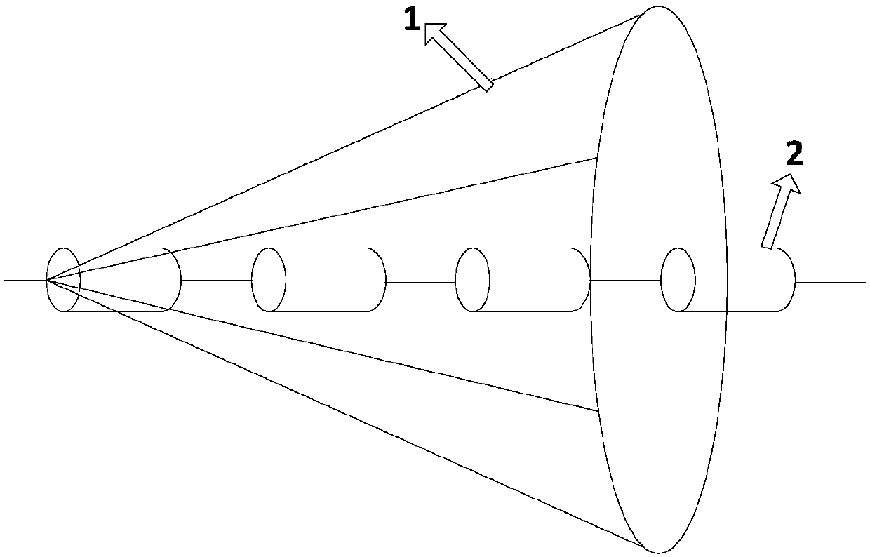
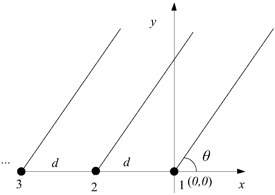
technical field [0001] The invention belongs to the research field of underwater acoustic direction finding, and in particular relates to a vector array starboard and starboard discrimination method based on the sound pressure and vibration velocity cross-spectrum method. Background technique [0002] In the research field of underwater acoustic direction finding, the direction finding of the towed linear array is based on the difference in time delay between the arrival of the sound source signal from different directions and the different array elements in the linear array. However, the hydrophones that make up the towed line array are usually non-directional, such as figure 1 As shown, 1 in the figure represents the conical surface, and 2 represents the hydrophone of the towed linear array. The responses of the incident signals on the conical surface with the same rotation angle to each element of the array are completely consistent, that is, the incident signals on the s...

Claims


Application Information

Patent Timeline
Patent Type & Authority Patents(China)
IPC IPC(8): G01S3/802
CPCG01S3/8027
Inventor 梅继丹朱英慧孙大军马超张珂
Owner HARBIN ENG UNIV
Learn More