Fuel injection valve

A technology for fuel injection valves and valve seats, which is applied in the direction of fuel injection devices, charging systems, engine components, etc. It can solve the problems of slow flow near the side, slow flow, and inability to effectively impart fuel vortex, so as to promote micro effect

Active Publication Date: 2015-03-11
HITACHI ASTEMO LTD
View PDF6 Cites 2 Cited by
  • Summary
  • Abstract
  • Description
  • Claims
  • Application Information

AI Technical Summary

Problems solved by technology

[0004] In the technology described in Patent Document 1, since the center of the side hole is located on the central axis of the lateral passage, when the fuel flows into the swirl chamber, the fuel collides with the side of the lateral passage, and the flow velocity near the center of the lateral passage is Slower flow near the sides
In particular, since the flow velocity outside the rotation direction of the fuel in the swirl chamber is slow, it may not be possible to effectively impart swirl to the fuel in the swirl chamber.

Method used


Image

  • Fuel injection valve
  • Fuel injection valve
  • Fuel injection valve

Examples


Embodiment 1

[0042] The fuel injection valve 1 of the first embodiment will be described.

[0043] [Structure of Fuel Injection Valve]

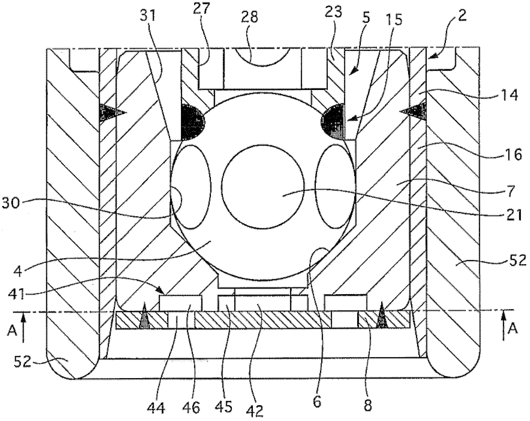
[0044] figure 1 is an axial sectional view of the fuel injection valve 1 . This fuel injection valve 1 is used in an automobile engine and the like.

[0045] The fuel injection valve 1 has: a magnetic cylinder body 2, a core cylinder body 3 housed in the magnetic cylinder body 2, a valve body 4 slidable in the axial direction, a valve shaft 5 integrally formed with the valve body 4, a The valve seat part 7 of the valve seat 6 which is blocked by the valve body 4, the nozzle plate 8 with the injection hole for injecting fuel when the valve is opened, the electromagnetic coil 9 which makes the valve body 4 slide in the valve opening direction when the valve is energized, and the sensor A yoke 10 for a magnetic induction line.

[0046] The magnetic cylinder body 2 is made of, for example, a metal tube formed of a magnetic metal material such as electroma...

Embodiment 2

[0095] The fuel injection valve 1 of the second embodiment will be described. The same reference numerals are assigned to the same components as those of the fuel injection valve 1 of the first embodiment, and description thereof will be omitted. The shape of the communication passage 45 of the fuel injection valve 1 of the second embodiment is different from that of the fuel injection valve 1 of the first embodiment.

[0096] [Structure of Vortex Chamber]

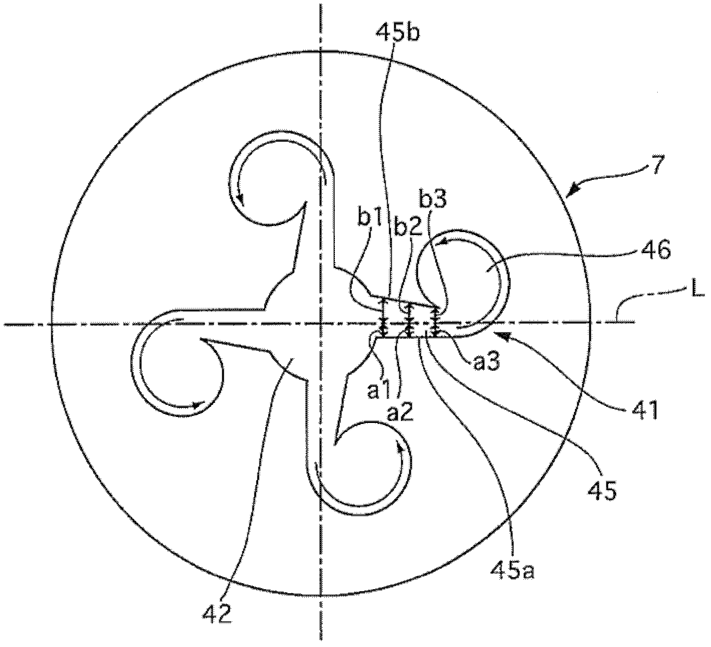
[0097] Figure 11 It is a plan view of the valve seat member 7 seen from the other end side. The swirl chamber 41 is composed of a communication path 45 and a swirl imparting chamber 46 . The communication path 45 is formed to extend radially from the central chamber 42 . A swirl imparting chamber 46 is formed at the tip of the radially extending communication path 45 . As far as the swirl imparting chamber 46 is concerned, in Figure 11 In the plan view shown, the side wall is formed in an involute curved shape. Wh...

Embodiment 3

[0115] The fuel injection valve 1 of the third embodiment will be described. The same reference numerals are assigned to the same components as those of the fuel injection valve 1 of the first embodiment, and description thereof will be omitted. The shape of the communication passage 45 of the fuel injection valve 1 of the third embodiment is different from that of the fuel injection valve 1 of the first embodiment.


PUM


Abstract

PROBLEM TO BE SOLVED: To provide a fuel injection valve device capable of efficiently adding a swirl to fuel in a swirl chamber.SOLUTION: A communication path is formed such that a distance between a first side surface on the radial outside where fuel rotates in a swirl adding chamber as a side surface of the communication path and a line extended in the radial direction of a center chamber is shorter than a distance between a second side surface in the radial inside where fuel rotates in the swirl adding chamber as the side surface of the communication path and a line extended in the radial direction of the center chamber.

Description

technical field [0001] The present invention relates to a fuel injection valve used as a fuel injection valve for an engine. Background technique [0002] As such a technique, the technique described in the following patent document 1 is disclosed. This publication discloses that when the valve is opened, fuel is supplied from the side hole to the swirl chamber through the lateral passage, and the fuel swirled in the swirl chamber is injected to the outside from the fuel injection hole. The transverse passage is formed so that the cross-sectional area decreases from the side hole toward the swirl chamber, and the flow velocity of the fuel increases. [0003] Patent Document 1: (Japanese) Unexamined Patent Publication No. 2003-336562 [0004] In the technology described in Patent Document 1, since the center of the side hole is located on the central axis of the lateral passage, when the fuel flows into the swirl chamber, the fuel collides with the side of the lateral passa...

Claims


Application Information

Patent Timeline
Patent Type & Authority Patents(China)
IPC IPC(8): F02M51/06F02M61/18
Inventor 大野洋史小林信章斋藤贵博中井敦士
Owner HITACHI ASTEMO LTD
Why Eureka
Try Eureka