Valve seat structure of fluid control valve

A technology for fluid control valves and valve seats, which is applied in the direction of lift valves, diaphragm valves, valve devices, etc., can solve the problem of uneven fluid flow, achieve the effect of suppressing flow fluctuations and reducing flow fluctuations

Active Publication Date: 2012-05-16
CKD
View PDF6 Cites 15 Cited by
  • Summary
  • Abstract
  • Description
  • Claims
  • Application Information

AI Technical Summary

Problems solved by technology

[0023] In this way, when the stroke difference between the valve seat 250, 350 and the metal diaphragm 260, 360 occurs after the valve is opened, the flow rate of the fluid flowing in the valve-opened state will be uneven. As the flow control accuracy of the valve, there is a problem that Cv The value drop is suppressed within 0.2 after valve opening, which is required in the field of precision parts manufacturing such as semiconductor manufacturing in recent years.
[0024] In addition, in the conventional metal diaphragm valve in which the second wall thickness t2 is formed at about 2.7 times the first wall thickness t1, although the sealing performance between the valve core and the valve seat member 150 is higher than that of a metal valve seat, it is different from that of the patent. In Documents 1 and 2, similarly, when the valve is in the open state, the flow rate of the flowing fluid becomes uneven, and the fluid cannot flow at a stable flow rate.

Method used


Image

  • Valve seat structure of fluid control valve
  • Valve seat structure of fluid control valve
  • Valve seat structure of fluid control valve

Examples


Embodiment 1

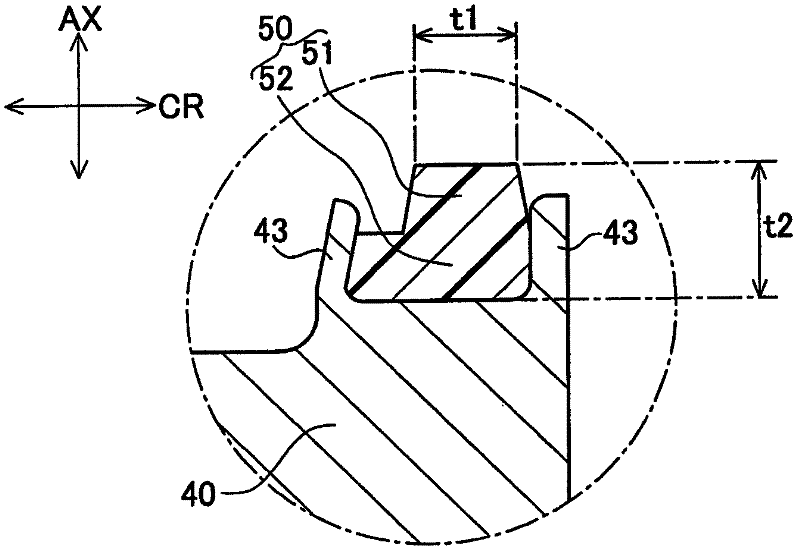
[0100] Embodiment 1 is the second wall thickness t2 such as figure 2 In the case of the valve seat member 50 shown in the shape of t2=1.25t1, specifically, for example, if the wall thickness (first wall thickness) of the valve seat portion 51 is set to t1=1.2 (mm), the valve seat member 50 A case where the height (second wall thickness) t2 = 1.5 (mm).

[0101] In Embodiment 1, the gas control valve 1 is in the closed state. After the valve is opened, the high-temperature gas continues to flow from the input port 41 through the valve chamber to the output port 42 for a long time. When a predetermined time has elapsed after the valve is opened, The stroke St of the diaphragm valve element 60 and the valve seat portion 51 of the valve seat member 50 when fully open and the Cv value at this time were measured.

[0102] Figure 5 It is a table about the relationship between the time after valve opening and the flow rate of flowing high-temperature gas comparing the valve seat st...

Embodiment 2

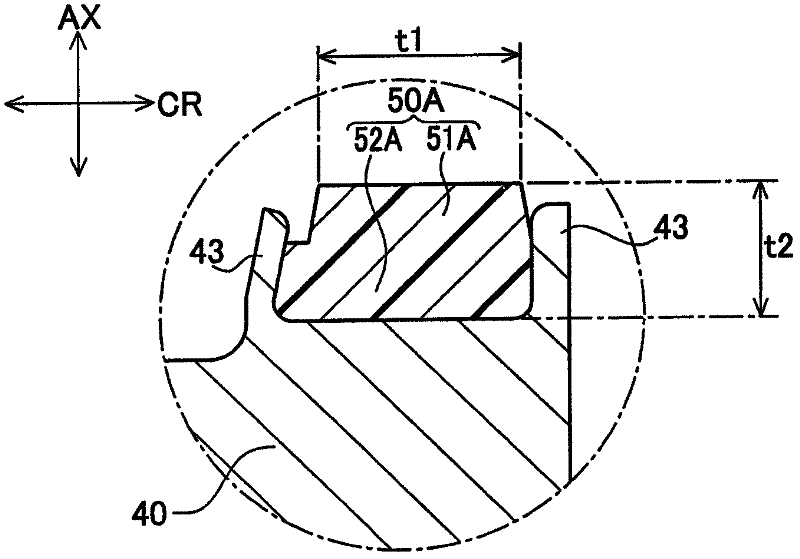
[0121] Same as Example 1, such as image 3 As shown, in the valve seat member 50A of the second embodiment, the fixed portion 52A is disposed between the grip portions 43, 43, and the grip portion 43 on the radially inner side in the radial direction CR and the grip portion 43 on the radially outer side face each other. The direction of caulking is carried out, thereby clamping along the radial direction CR and being fixed to the valve body 40 .

[0122] In this example, if image 3 As shown in the shape of the valve seat member 50A, when the second wall thickness t2 is t2=0.63t1, specifically, for example, if the wall thickness of the valve seat portion 51A is t1=2.2 (mm), the height of the valve seat member 50A is It is t2=1.5 (mm). In this case, the sinking amount of the valve seat portion 51A is 0.13 mm, and the restoring amount of the valve seat portion 51A is 0.10 mm.

[0123] In addition, as a modified example of Embodiment 2, Figure 4 An explanatory diagram showin...


PUM


Abstract

In a valve seat structure of a fluid control valve comprising a valve element(60), a body formed with an inlet port (41) and an outlet port (42), and a valve seat member (50)provided in the body, the fluid control valve being configured to bring the valve element into or out of contact with the valve seat member to control the flow of a fluid, the valve seat member is formed in a ring shape and includes a valve seat portion (51) with which the valve element will come into our out of contact. Assuming that a thickness of the valve seat portion in a radial direction of the valve seat member is a first thickness t1 (0<t1), a second thickness t2 corresponding to a height of the valve seat member in a direction along an axis of the fluid control valve is determined in a range of 0.5 t1<=t2<=1.5 t1.

Description

technical field [0001] The present invention relates to a valve seat structure of a fluid control valve that controls the flow of fluid. More specifically, it relates to a valve seat structure of a diaphragm valve for controlling the flow of a fluid such as a high-temperature gas by abutting or separating a diaphragm valve element from a valve seat in, for example, a semiconductor manufacturing device. Background technique [0002] In the semiconductor manufacturing process or liquid crystal panel manufacturing process, etc., when H 2 When supplying or shutting off high-temperature gas such as gas and Ar gas to semiconductor manufacturing equipment, for example, metal diaphragm valves disclosed in Patent Documents 1 and 2 are used as fluid control valves for controlling the flow of the high-temperature gas. [0003] Figure 6 and Figure 7 A diagram illustrating the metal diaphragm valve of Patent Document 1 is shown. Such as Figure 6 and Figure 7 As shown, Patent Docu...

Claims


Application Information

Patent Timeline
Patent Type & Authority Applications(China)
IPC IPC(8): F16K7/12
CPCF16K1/42F16K1/425F16J3/02F16K7/12
Inventor 青山达人
Owner CKD
Why Eureka
Try Eureka