Pressure-stabilizing valve for liquid pipeline

A technology of liquid pipelines and pressure stabilizing valves, applied in safety valves, balance valves, valve devices, etc., can solve problems affecting wafers, machine 9 alarms, wafer scrapping, etc., to reduce pressure fluctuations and flow fluctuations , improve the service life and reduce the effect of impact

Active Publication Date: 2018-12-25
WUHAN XINXIN SEMICON MFG CO LTD
View PDF7 Cites 5 Cited by
  • Summary
  • Abstract
  • Description
  • Claims
  • Application Information

AI Technical Summary

Problems solved by technology

like Figure 4 As shown, wherein the horizontal axis is time, and the vertical axis is pressure. Although the energy storage device 11 in the liquid pipeline can provide compensation for the pressure drop in the circuit of the liquid pipeline, due to the piston stroke in the reciprocating diaphragm pump 10 The defect of switching the liquid supply cylinder 12 will occur in the middle section and the end section, resulting in a large pressure fluctuation in the main circuit, especially in a long pipeline with a large pressure loss, so that the pipeline connected The pressure fluctuation at the 9th end of the machine reaches 0.12Mpa~0.25Mpa
However, the machine 9 has a certain range of pressure fluctuations and flow fluctuations. For example, the pressure fluctuation of the chemical mechanical polishing (CMP) machine 9 is generally set to ± 20%, and the flow fluctuation is generally set to ± 10%. When the pressure fluctuation or flow fluctuation exceeds this When it is within the range, it will cause the machine 9 to alarm, which will affect the wafer being ground, and even cause the wafer to be scrapped in severe cases.
Moreover, periodic hydraulic shocks are easy to damage pipeline components and affect the life of the machine 9

Method used


Image

  • Pressure-stabilizing valve for liquid pipeline
  • Pressure-stabilizing valve for liquid pipeline
  • Pressure-stabilizing valve for liquid pipeline

Examples


Embodiment Construction

[0030] The technical solutions in the embodiments of the present invention will be clearly and completely described below in conjunction with the accompanying drawings in the embodiments of the present invention. Obviously, the described embodiments are only part of the embodiments of the present invention, rather than all the embodiments. Based on the embodiments of the present invention, all other embodiments obtained by those of ordinary skill in the art without creative work shall fall within the protection scope of the present invention.

[0031] It should be noted that the embodiments of the present invention and the features in the embodiments can be combined with each other if there is no conflict.

[0032] The following describes the progress of the present invention with reference to the drawings and specific embodiments, but it is not a limitation of the present invention.

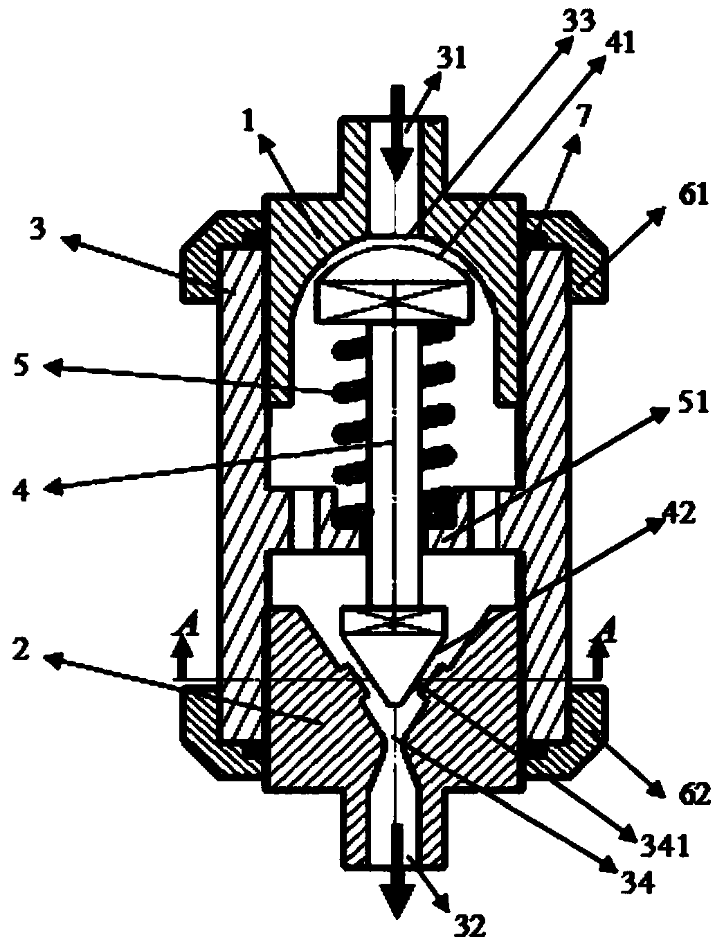
[0033] figure 1 Is a longitudinal sectional view of an embodiment of a pressure stabilizing valve ...


PUM


Abstract

The invention provides a pressure-stabilizing valve for a liquid pipeline. The pressure-stabilizing valve comprises a valve body, wherein a liquid inlet is formed in one end of the valve body; the inner side of the liquid inlet comprises an inner concave surface; a liquid outlet is formed in the other end of the valve body and comprises a through hole of which the inner wall is gradually reduced from the direction of the liquid inlet to the liquid outlet; a valve rod is movably connected to the inner part of the valve body through an elastic element; the electric element forms an elastic forcepointing to the direction of the liquid inlet between the valve body and the valve rod; one end, facing the liquid inlet, of the valve rod, is matched with the inner concave surface; preset distanceis formed between the other end, facing the liquid inlet, of the valve rod and the inner concave surface when the valve rod is positioned at the maximum point of shift motion in the direction of the liquid inlet; the end, facing the liquid outlet, of the valve rod, is matched with the through hole in shape; the end, facing the liquid outlet, of the valve rod, reduces liquid flow of the through hole when the valve rod moves towards the direction of the liquid outlet. The pressure-stabilizing valve provided by the invention has the beneficial effects that liquid throttling is automatically controlled, and further pressure fluctuation and flow fluctuation of liquid are reduced; in addition, the influence of pressure fluctuation and flow fluctuation on products is reduced.

Description

Technical field [0001] The present invention relates to the technical field of semiconductor processing, in particular to a pressure stabilizing valve used for a liquid pipeline of a semiconductor processing equipment. Background technique [0002] In the prior art, the liquid raw material used for processing in the semiconductor processing machine 9 is usually pumped to the machine 9 through a reciprocating diaphragm pump 10 and a pipeline connected to the reciprocating diaphragm pump 10, such as image 3 As shown, compressed air is connected to the reciprocating diaphragm pump 10, and the reciprocating diaphragm pump 10 sucks in liquid from the liquid supply cylinder 12 and presses the liquid into the downstream pipeline. The liquid flows through the energy storage device 11 and returns to the liquid supply. The cylinder 12 and a plurality of machines 9 are connected in parallel on the main circuit. Such as Figure 4 As shown, the horizontal axis is time and the vertical axis is...

Claims


Application Information

Patent Timeline
Patent Type & Authority Applications(China)
IPC IPC(8): F16K17/26F16K17/34
CPCF16K17/26F16K17/34
Inventor 易洪昇
Owner WUHAN XINXIN SEMICON MFG CO LTD
Why Eureka
Try Eureka