High-speed visual positioning device and method applied to substrate

A visual positioning and visual device technology, which is applied in the direction of using optical devices, measuring devices, lighting devices, etc., can solve the problems of non-positioning, skewed board, and large variation of manual board operation efficiency, so as to improve the accuracy and artificial intelligence. cost reduction effect

Inactive Publication Date: 2013-07-17
D TEK TECHNOLOGY CO LTD
View PDF6 Cites 0 Cited by
  • Summary
  • Abstract
  • Description
  • Claims
  • Application Information

AI Technical Summary

Problems solved by technology

[0005] 1. Since there is currently no automatic production equipment for the strip-shaped light bar structure or the substrate, it is all done manually, for example, manually attach the substrate to the carrier, and then print the barcode of the substrate; and then manually Carry out board disassembly; then, manually tape the board again, and then carry out printing / part placement / reflow and other processes
It is obvious that the accuracy of the boards made by the above-mentioned manual method is not good. In addition to the error of manual lamination, the accuracy cannot be effectively controlled due to the bending or offset of the long strip substrate itself. For example, the board is skewed, Not positioned, etc., resulting in poor printing of barcodes or poor printing and placement, etc.
[0006] 2. Bearing in mind 1, because the accuracy cannot be effectively controlled, a large number of personnel must be arranged to carry out various inspection operations, such as product appearance inspection, inspection of LEDs for offset, etc., so labor costs also cause the production unit of LED light bar structure burden
[0007] 3. Moreover, the efficiency of manual pasting operations varies greatly, and it is difficult to control regardless of quality or speed

Method used


Image

  • High-speed visual positioning device and method applied to substrate
  • High-speed visual positioning device and method applied to substrate
  • High-speed visual positioning device and method applied to substrate

Examples


Embodiment Construction

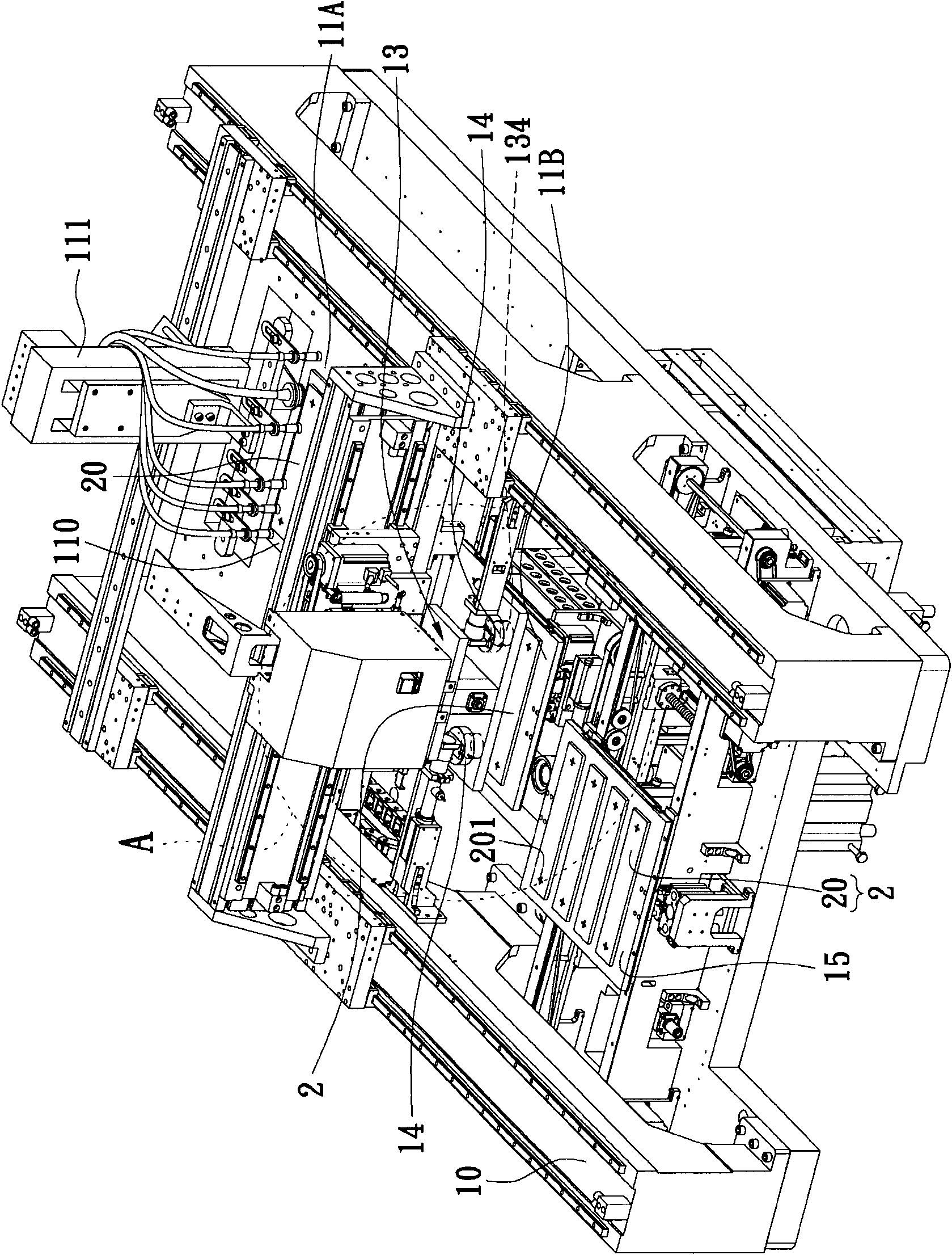
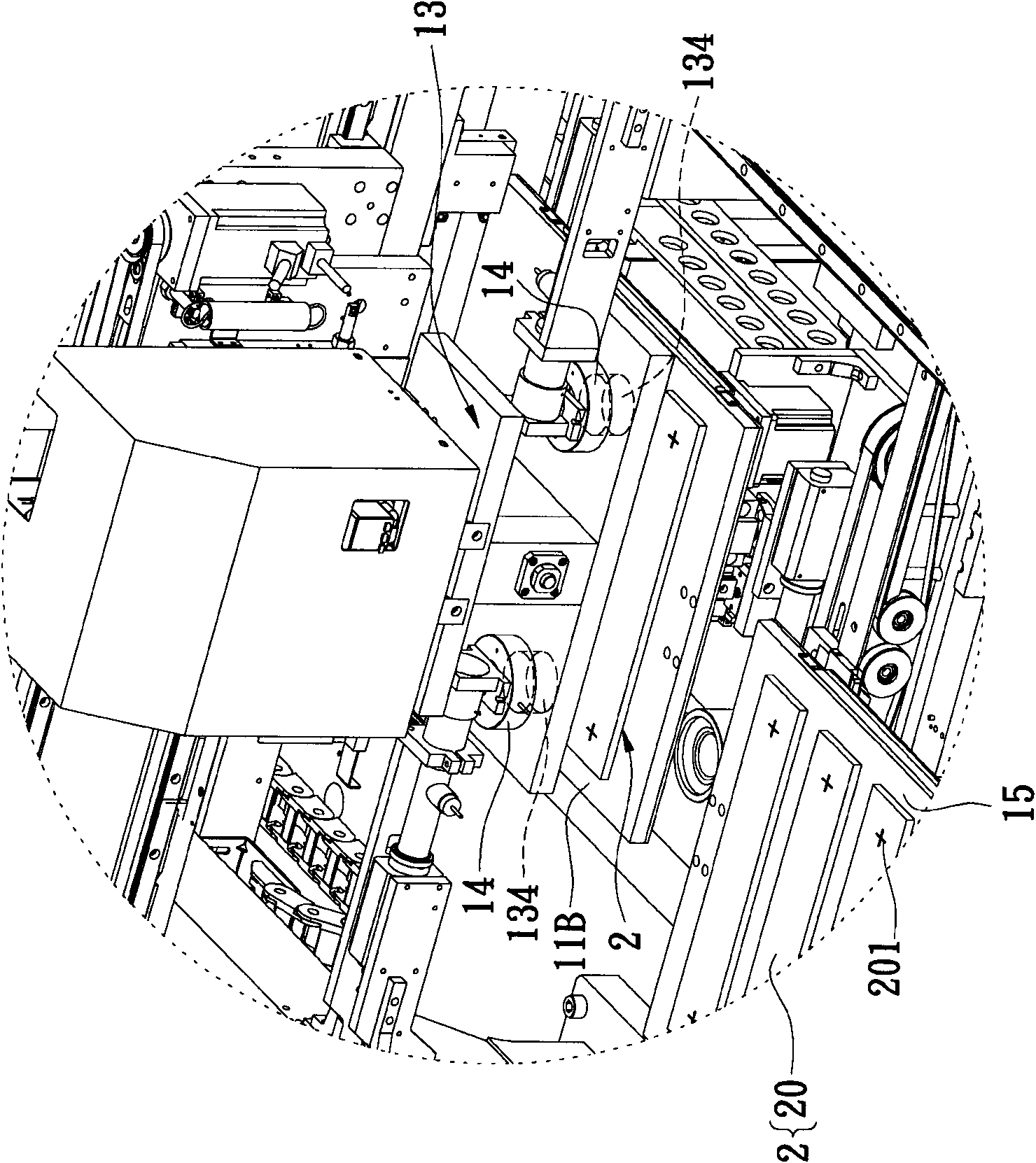
[0033] The present invention proposes a high-speed visual positioning device and method suitable for substrates, which can be used to quickly move substrates, such as strip-shaped modules of light-emitting diodes, to solve the problem that traditional machines cannot be used for strip-shaped light-emitting diodes. Shaped modules, so the production unit can be manufactured for the purpose of improving production efficiency.

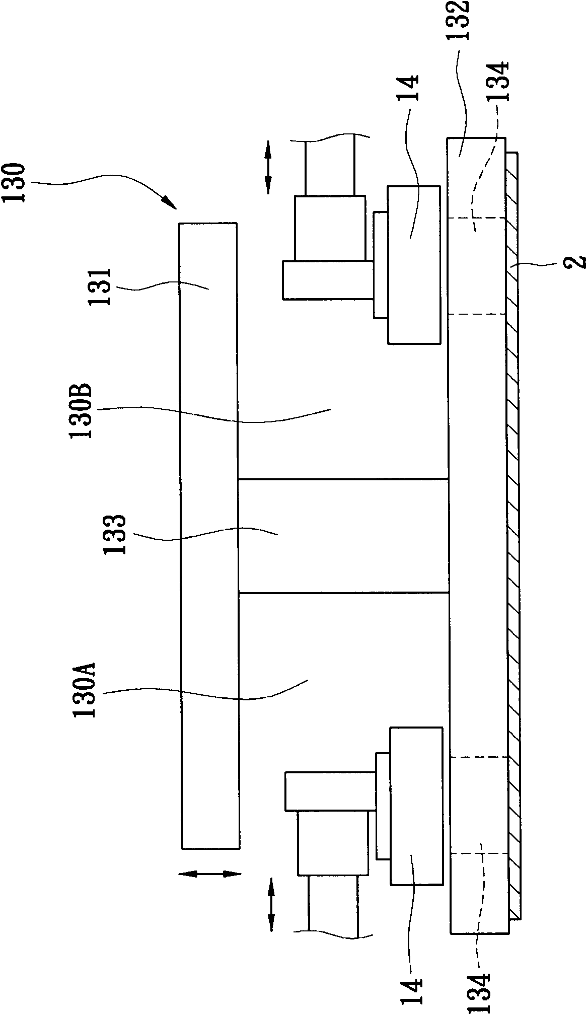
[0034] First, see Figure 1 to Figure 1B As shown, the visual positioning device of the present invention includes: a frame body 10, a temporary storage area 11A located on the frame body 10, a positioning area (also known as a material retrieval area) 11B located on the frame body 10, a moving Positioning device 13, at least two visual devices 14 arranged on the frame body and a carrier plate 15 placed on the frame body 10, and the function of the visual positioning device is to place a plurality of substrates, such as strips of light emitting diodes Mod...


PUM


Abstract

The invention discloses a high-speed visual positioning device and method applied to a substrate. The high-speed visual positioning device applied to the substrate comprises a frame, a temporary storage area, a positioning area, a transport positioning device, at least two visual devices arranged on the frame and a carrier plate, wherein the transport positioning device is movably arranged on theframe and is used for absorbing and transporting a plurality of substrates; the transport positioning device comprises an I-shaped absorbing head which is used for absorbing the plurality of substrates sequentially; the at least two visual devices correspond to the I-shaped absorbing head and are used for capturing an image of each substrate absorbed by the transport positioning device so as to position the plurality of substrates; and the carrier plate is arranged on the frame.

Description

technical field [0001] The invention relates to a high-speed visual positioning device and method suitable for substrates, in particular to a high-speed, high-precision high-speed visual positioning device and method suitable for strip modules of light-emitting diodes. Background technique [0002] The advantages of light-emitting diodes are: (1) the energy conversion efficiency of light is high, so it saves power; (2) the response time is fast, and it can reach a high flicker frequency; (3) it is more environmentally friendly, there is no harmful substance of mercury, and it is easy to use. recycling and more. In addition, it also has the advantages of resistance to mechanical shocks such as shocks, small size, easy focusing, and wide color gamut. Therefore, "light emitting diodes" are also widely used in various light source fields. [0003] For example, the backlight module of the light source of the display panel can be roughly divided into a direct-type light source o...

Claims


Application Information

Patent Timeline
Patent Type & Authority Patents(China)
IPC IPC(8): F21V19/00F21S4/00G01B11/00
Inventor 费耀祺
Owner D TEK TECHNOLOGY CO LTD
Why Eureka
Try Eureka