Layered double-channel underground grouting structure and method

A dual-channel, operating method of technology, applied in the field of grouting reinforcement of soft soil foundations and anti-seepage plugging, can solve the problems of grouting hole blocking, grouting hole being easily blocked, high calcium carbonate output, etc.

Pending Publication Date: 2021-05-18
DALIAN UNIV OF TECH
View PDF0 Cites 2 Cited by
  • Summary
  • Abstract
  • Description
  • Claims
  • Application Information

AI Technical Summary

Problems solved by technology

In addition, during the MICP reinforcement process, due to the rapid generation of calcium carbonate, the grouting holes are easily blocked, and the blockage of the grouting holes must be considered in the design of the grouting process
[0005] If only a single point source is used in the grouting process to inject the grout into the target soil layer, the grouting time will often be too long due to the large flow path
In addition, existing studies have shown that the adsorption of microorganisms in porous media exhibits an exponential decay distribution along the injection direction, and the decreasing amount of microorganisms adsorbed on the soil along the grouting direction leads to a decrease in calcium carbonate production along the grouting direction.
Therefore, relying on a single point source grouting for a long time may lead to excessive calcium carbonate production near the grouting opening, or even completely block the flow path, while in the area far from the grouting opening, the calcium carbonate production is insufficient
Moreover, in actual engineering, the geological conditions of the target areas that need to be reinforced or seepage prevention and plugging are not consistent, and the permeability differences are significant
The flow law of grouting fluid in formations with different permeability characteristics is complex, and the flow path is difficult to determine and control

Method used


Image

  • Layered double-channel underground grouting structure and method
  • Layered double-channel underground grouting structure and method

Examples


Embodiment Construction

[0029] In order to enable those skilled in the art to better understand the technical solutions of the present invention, the present invention will be further described in detail below in conjunction with the accompanying drawings and specific embodiments:

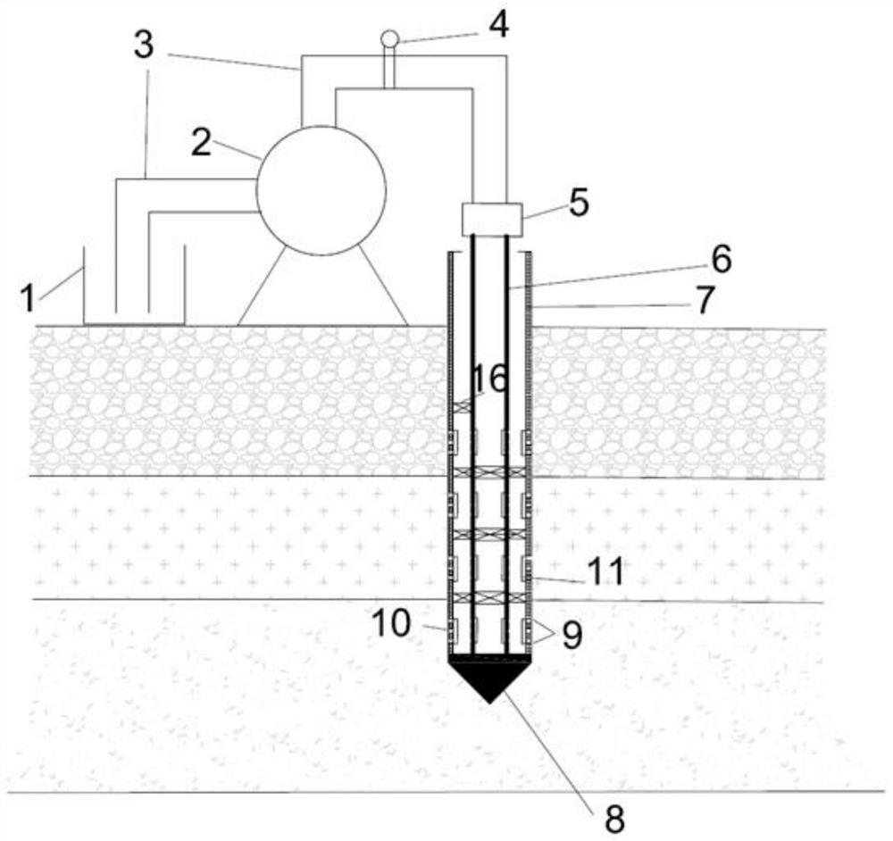
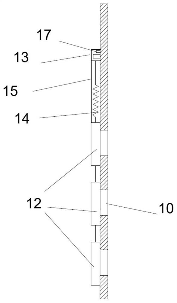
[0030] Such as Figure 1-2As shown, a layered double-channel underground grouting structure is disclosed in this example. The liquid reservoir 1 is made of a large plastic bucket, and the capacity can be adjusted in real time according to the preset grout volume. The inner diameter of the PE hose 3 is 32 mm, one end of which is placed on the bottom of the liquid reservoir, and the other end passes through the constant pressure water pump 2 and is connected to the pipe joint 5 . An electromagnetic flowmeter 4 is arranged on the PE hose 3 . The constant pressure water pump 2 can adjust the grouting pressure, and can adopt a suitable grouting pressure for areas to be grouted with different depths and different permeability....


PUM


Abstract

The invention belongs to the technical field of grouting reinforcement of soil foundations and seepage prevention and leakage stoppage, and particularly relates to a layered double-channel underground grouting structure and method. The structure comprises a grout supply system, a grouting system and a monitoring system. Layered grouting of soil can be achieved through a series grouting sleeve and a tension fixing separator in the grouting system. Time-sharing and channel-dividing grouting of different types of grouting liquid can be achieved through the synergistic effect of double-channel grout supply, grouting holes capable of being opened and closed and the tension fixing separator. The cementation degree of the soil can be monitored and evaluated in real time through an acoustic detector. According to the structure, the requirements for different cementation degrees in stratum grouting reinforcement can be met only through one-time hole forming, the moving frequency of a grouting pipe is reduced, and the working efficiency and the grout utilization rate are improved. Through the layered grouting and cementation degree real-time monitoring technology, grout waste is avoided, and the grout utilization rate is increased. The structure has important significance in popularizing MICP underground grouting in foundation reinforcement or seepage prevention and leakage stoppage and other engineering application.

Description

technical field [0001] The invention belongs to the technical field of grouting for strengthening soft soil foundation and anti-seepage and plugging, and relates to a layered double-channel underground grouting structure and a method. Background technique [0002] The grouting method is a commonly used foundation reinforcement, seepage prevention and plugging treatment method. By injecting cementing fluid into the target area, cracks in rocks and cement liners can be successfully repaired, dam erosion can be reduced, pipeline leakage can be prevented, polluted water sources can be isolated, soil permeability can be reduced to reduce seepage deformation, etc. Traditional grouting fluids, such as cement grout, have a high viscosity. When applied to fine-grained soil reinforcement or repair of tiny cracks, grouting is difficult, and even the original structure may be split and damaged due to high grouting pressure. Although chemical grout has good groutability, the existing gr...

Claims


Application Information

Patent Timeline
Patent Type & Authority Applications(China)
IPC IPC(8): E02D3/12E02D1/00
CPCE02D1/00E02D3/12
Inventor 田志锋唐小微修志龙薛志佳李涛王晨牟
Owner DALIAN UNIV OF TECH
Why Eureka
Try Eureka