


Quick Research
Generate reliable direction feasibility study reports for your R&D in just a few steps.

Technical Q&A
Discover and master advanced knowledge NOW. Basics, ideas, possibilities, all at once.

Find Solutions
As an expert in R&D theories, this can generate solutions to your technical problems instantly.

Evaluate Feasibility
Analyze your overall solution with one click, know your potential R&D risks in advance.

Monitor Landscape
Get weekly tech updates, stay abreast of the latest tech innovations and key insights.
Ultrasonic surgery device, ultrasonic surgery system, and method for reducing cavitation
A surgical device, ultrasonic technology, applied in surgery, parts of surgical instruments, medical science, etc., can solve problems such as cavitation
- Summary
- Abstract
- Description
- Claims
- Application Information
AI Technical Summary
Problems solved by technology
Method used
Image

Examples
no. 1 approach
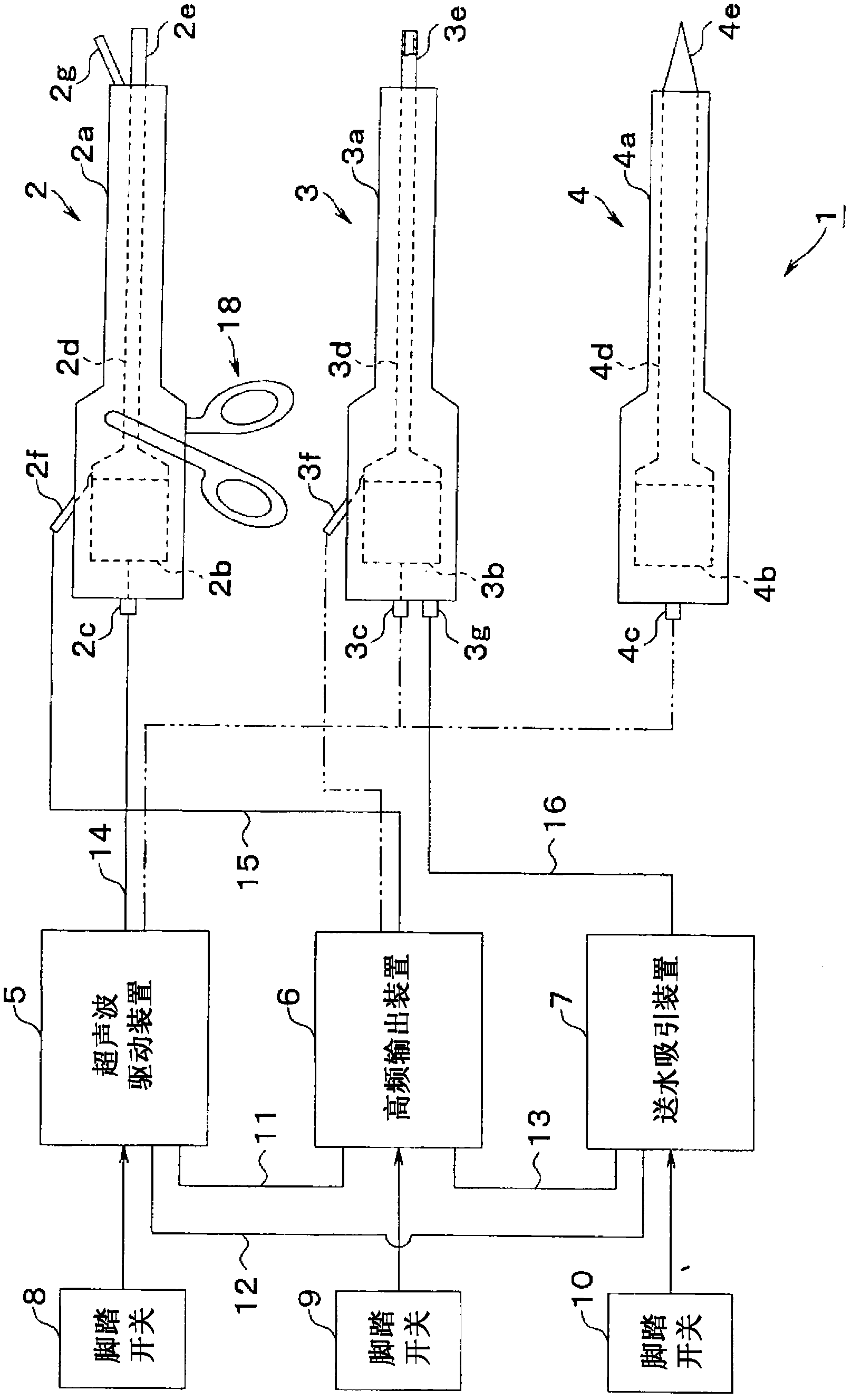
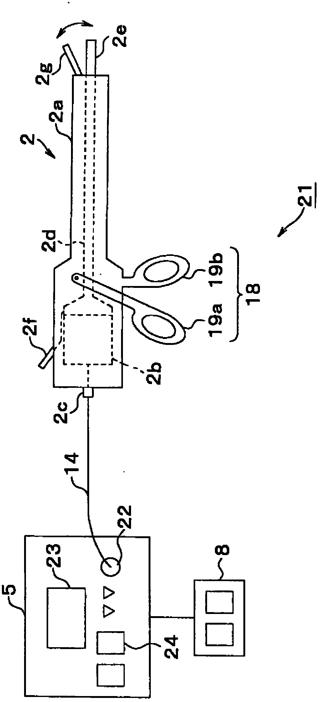
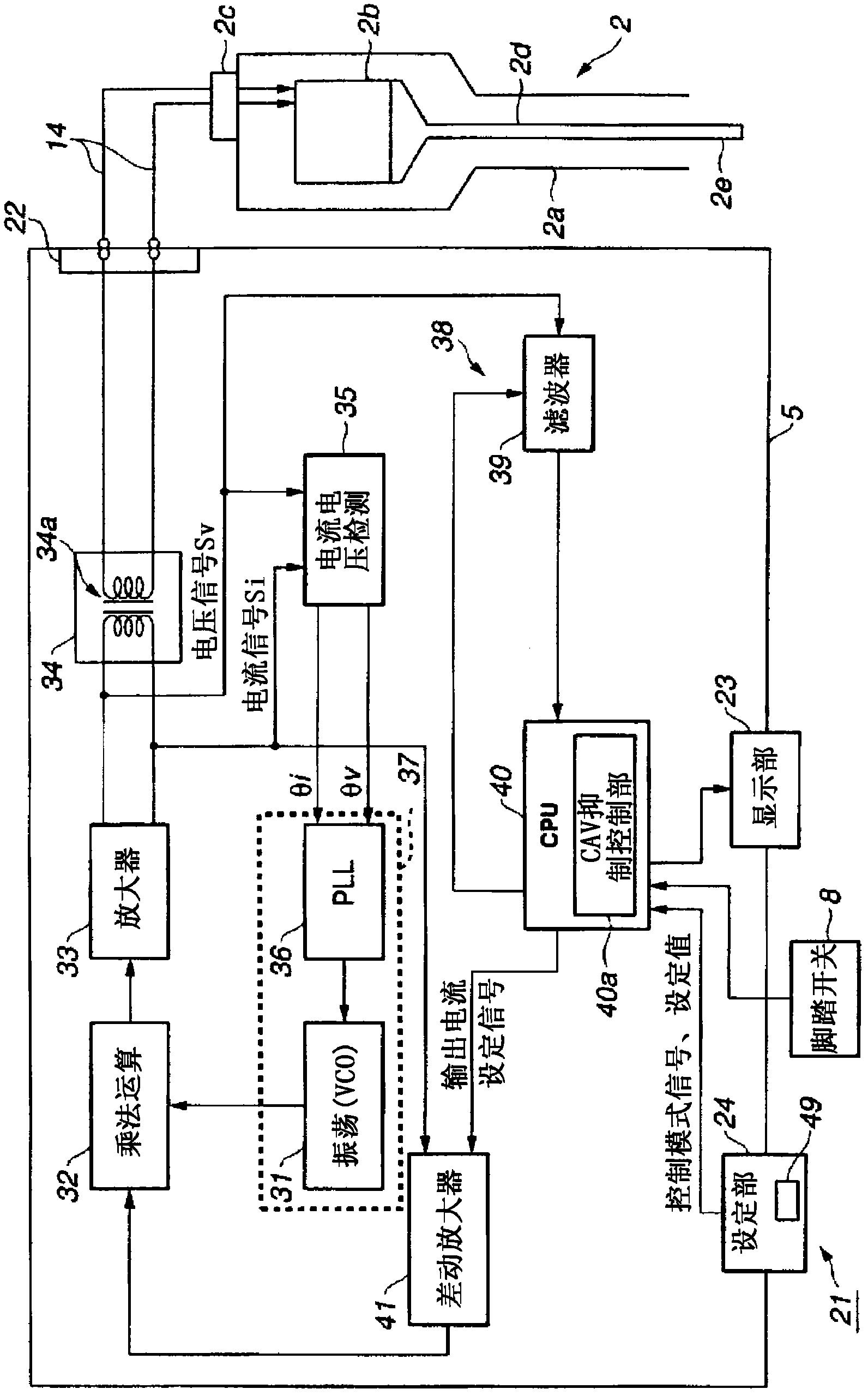
[0043] Figure 1 to Figure 7 Regarding the first embodiment of the present invention, figure 1 Showing the configuration of the ultrasonic surgical system according to the first embodiment of the present invention, figure 2 Showing the structure of the ultrasonic surgical apparatus of the first embodiment, image 3 shows the structure of the ultrasonic drive device, Figure 4A The frequency distribution of the current signal detected from the drive signal when cavitation occurs and when no cavitation occurs is shown. Here, the frequency distribution of the current signal is shown, but the same tendency applies to the voltage signal.
[0044] Figure 4B to Figure 4D An example of the filter characteristics of the filter circuit is shown, Figure 5 shows a configuration example of a filter circuit, Figure 6 A method of treatment using an ultrasonic surgical device is shown, Figure 7 show inhibition Figure 6 Inhibition method of cavitation generation level.
[0045]...
no. 2 approach
[0174] Then refer to Figure 10 A second embodiment of the present invention will be described. Figure 10 The configuration of an ultrasonic surgical apparatus 21C according to the second embodiment of the present invention is shown. In the first embodiment, an apparatus and a method for automatically controlling cavitation elimination in the cavitation reduction control mode have been described.
[0175] On the other hand, this embodiment is configured to include a notification unit that notifies the user, the operator, of the generation level of cavitation by quantitatively displaying the level of occurrence of cavitation. The set value of the fixed part 24 is manually set so that it may be set to a desired cavitation level.
[0176] The ultrasonic surgical device 21C is configured to image 3 In the ultrasonic drive device 5 having the structure, an A / D conversion circuit 51 and an indicator 52 as a notification section are further provided, thereby constituting an ultr...
no. 3 approach
[0211] Next, refer to Figure 13 A third embodiment of the present invention will be described. In this embodiment, the control mode can be automatically set according to the handpiece 1 or the probe 1a actually used.
[0212] Figure 13 The configuration of an ultrasonic surgical apparatus 21D according to the third embodiment is shown. In this embodiment, a recognition unit for recognizing the handpiece 1 is provided as described below, and the control mode can be switched according to the recognition result.
[0213] Regarding this ultrasonic surgical device 21D, for example, in Figure 8 In the ultrasonic surgical device 21B, each hand piece 1 (in Figure 13 Where I=2) For example, ROMIh forming an identifier is embedded in, for example, the base end of the probe Ia, and the identifier is used to generate handpiece type information (also referred to as a type signal).
[0214] In addition, the ultrasonic drive device 5D includes an identification unit 66 having a comm...
PUM
 Abstract
Description
Claims
Application Information
 - R&D Engineer
- R&D Manager
- IP Professional
- Industry Leading Data Capabilities
- Powerful AI technology
- Patent DNA Extraction
Browse by: Latest US Patents, China's latest patents, Technical Efficacy Thesaurus, Application Domain, Technology Topic, Popular Technical Reports.
© 2024 PatSnap. All rights reserved.Legal|Privacy policy|Modern Slavery Act Transparency Statement|Sitemap|About US| Contact US: help@patsnap.com