Method and system for channel state information feedback under CoMP (cooperative multi-point) mode

A channel information feedback and information feedback technology, which is applied in the transmission system, digital transmission system, radio transmission system, etc., can solve the problems of being unable to dynamically support single-cell CSI and adapting to dynamic switching of different transmission technologies.

Active Publication Date: 2012-05-30
ZTE CORP
View PDF4 Cites 24 Cited by
  • Summary
  • Abstract
  • Description
  • Claims
  • Application Information

AI Technical Summary

Problems solved by technology

[0005] However, there is still a problem in CoMP transmission: in the same node, when there are users served by multi-nodes cooperatively, there will be target users of coordinated services and target users of non-coordinated services in the same cell
[0006] At present, there is no relatively complete tech

Method used


Image

  • Method and system for channel state information feedback under CoMP (cooperative multi-point) mode
  • Method and system for channel state information feedback under CoMP (cooperative multi-point) mode
  • Method and system for channel state information feedback under CoMP (cooperative multi-point) mode

Examples


Embodiment 1

[0086] Example 1: Periodic feedback extension

[0087] During periodical feedback, for the channel information of other coordinated cells, when the channel information of other cells is fed back on the PUCCH, configuration may be performed in the following manner.

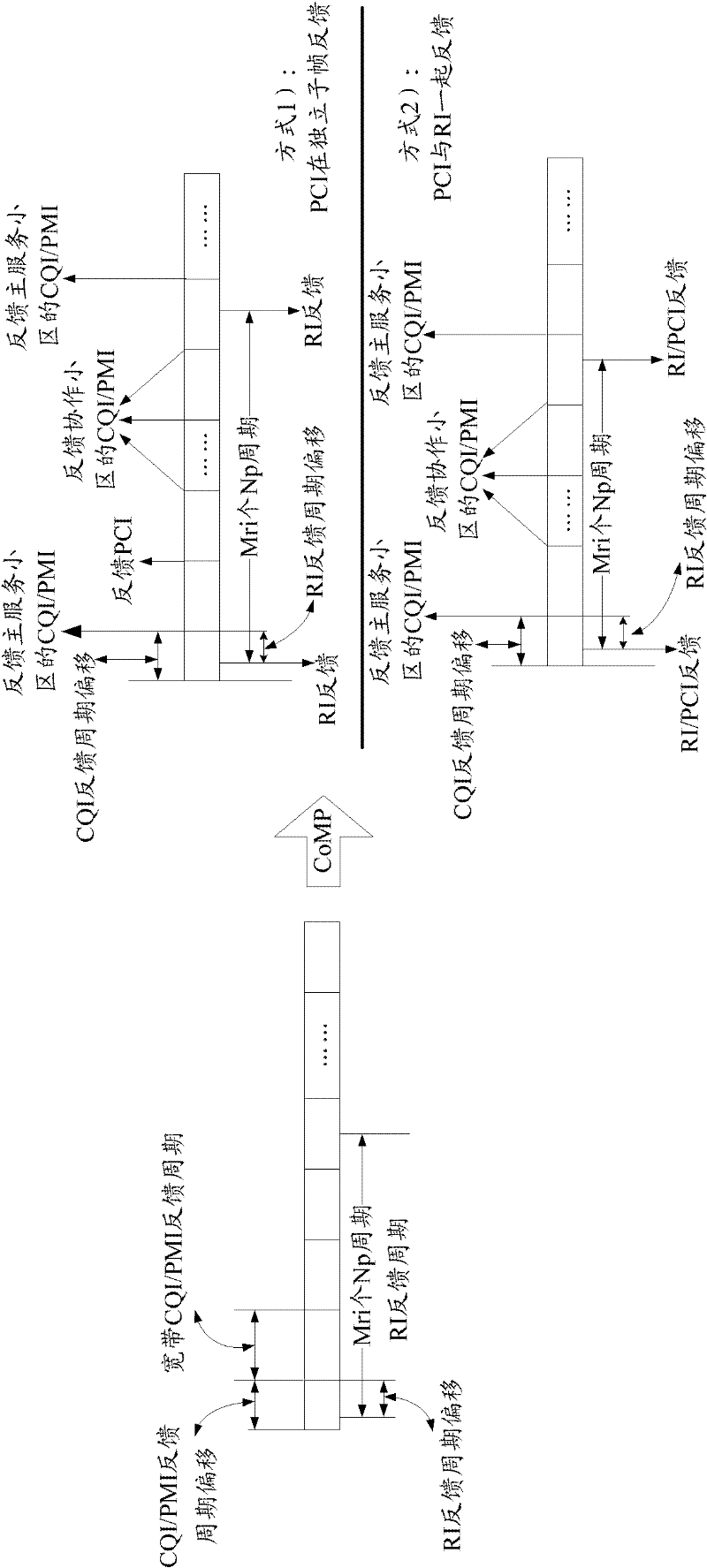
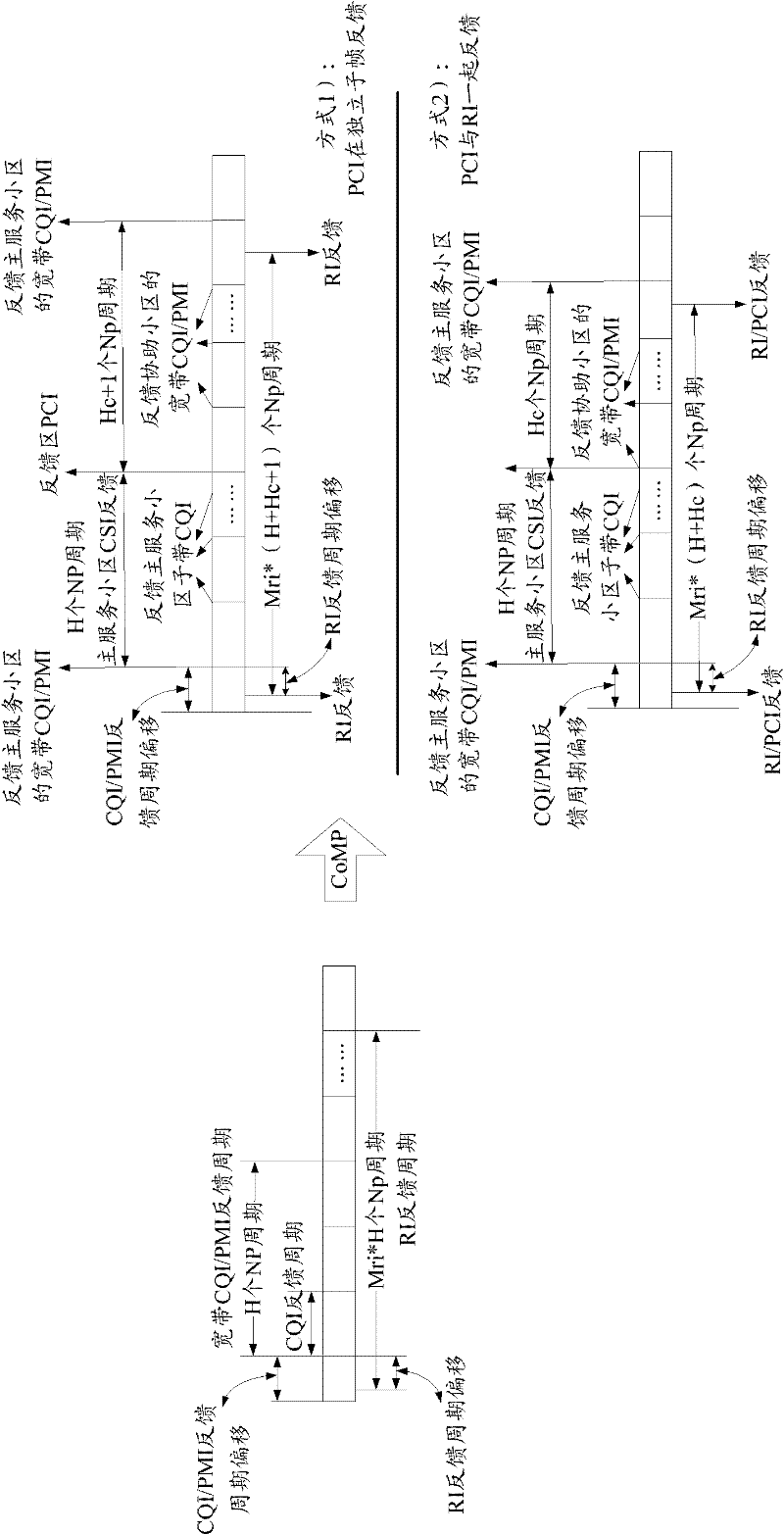
[0088] 1. Using broadband CQI and PMI feedback, such as figure 1 shown;

[0089] In way 1), by configuring Mri, where Mri is a parameter indicating the configuration of the RI transmission cycle, the CQI / PMI of the primary serving cell and the coordinated cell are fed back between two RI feedbacks. Wherein, when the PCI needs to be fed back, the PCI can be fed back on an independent feedback period between the main serving cell feeding back the CQI / PMI and the coordinated cell feeding back the CQI / PMI (such as figure 1 in the way 1). In this extended mode, the Mri value configured by the high layer needs to be greater than or equal to the period required for the broadband CQI / PMI and PCI feedback of the main ser...

Embodiment 2

[0102] Embodiment 2: PUSCH feedback extension

[0103] In LTE R8, the feedback of CSI information on PUSCH only exists in two cases. One case is that there is uplink shared data during periodic feedback. At this time, CSI information is transmitted on PUSCH, and the format is the same as the feedback format on PUCCH. same. Another case is aperiodic feedback. When aperiodic feedback is configured in the PDCCH, the CSI information is fed back in accordance with the aperiodic feedback mode configured by the high layer. Normally, acyclic feedback is only performed in the following two cases:

[0104] When the DCI format of downlink transmission is 0, and the CQI request in DCI format 0 is set to 1;

[0105] When the CQI request of the corresponding grant is set to 1 for random access.

[0106] When considering the extension of CoMP, mainly consider the case where the CQI request in the downlink DCI format 0 is set to 1. In practical applications, two methods of PUSCH feedback ...


PUM


Abstract

The invention discloses a method and a system for channel state information feedback under a CoMP (cooperative multi-point) mode. In the method, channel state information feedback of a main service area and other cooperative areas except the main service area is performed by a terminal under a cooperative multi-point transmission mode according to feedback modes and/ or different granularities of the service areas, wherein the main service area refers to an area for sending physic downlink control information to users, and the cooperative areas refer to one or a plurality of areas which need measurement and feedback of channel state information. A technique of channel state information feedback under the CoMP mode is realized by means of the method and the system, and the method and the system are supportable for the channel state information feedback under the CoMP mode. Furthermore, the method and the system can dynamically support single-area CSI (channel state information) feedback and multi-area CSI feedback so as to adapt to dynamic switching among different transmission techniques.

Description

technical field [0001] The invention relates to the communication field, in particular to a method and a system for channel information feedback in a CoMP (coordinated multi-point transmission) mode. Background technique [0002] With the introduction of LTE-A requirements, people pay more and more attention to the average spectrum efficiency of the cell and the spectrum efficiency of the cell edge. In comparison, the spectral efficiency at the edge of the cell is the most concerned, mainly because the uplink and downlink of the LTE-A system are all frequency division systems with OFDM (or some variation of OFDM) as the basic multiple access multiplexing method. . Different from the traditional wireless communication system with CDMA as the basic multiple access multiplexing method, the LTE-A system has no processing gain. Because the frequency division is completely orthogonal inside the cell, there is almost no interference problem, but the interference processing at the ...

Claims


Application Information

Patent Timeline
IPC IPC(8): H04L1/16H04L1/00
CPCH04L1/0026H04B7/0417H04B7/04H04B7/024H04B7/0626
Inventor 孙云锋郭森宝陈艺戬张晨晨张峻峰
Owner ZTE CORP
Why Eureka
Try Eureka