
Swing-up environment-friendly pit garbage compression station

A garbage compression station and garbage compression technology, which is applied in the directions of garbage conveying, garbage collection, loading/unloading, etc. It can solve the problems of low cleaning and transportation cost, low cost, low lifting weight, etc., and achieve good compression effect and high compression density. , The effect of large lifting weight

Active Publication Date: 2014-10-22
德阳旌卫环保工程有限公司
View PDF9 Cites 0 Cited by
  • Summary
  • Abstract
  • Description
  • Claims
  • Application Information

AI Technical Summary

Problems solved by technology

The pressure of vertically compressing garbage is high, the garbage is lumped, and the cost of garbage removal is low, but the equipment is expensive, the cost of housing construction is high, and the environmental protection effect is poor; After the garbage in the compressed box is compressed, the lifting device installed on the box lifts the box from the pit for transportation. The cost of the entire garbage compression treatment equipment is relatively low, limited by the low lifting weight, the compressed Garbage should not be too much, otherwise it cannot be lifted normally from the pit, resulting in low efficiency of garbage compression treatment; the lifting method is generally vertical lifting, and the garbage transfer vehicle is too close to the discharge port of the lifted garbage compression box When close, the wheels are easy to sink into pits; when the garbage is compressed, the pressure is small, and the garbage is not easy to form a block

Method used


Image

  • Swing-up environment-friendly pit garbage compression station
  • Swing-up environment-friendly pit garbage compression station
  • Swing-up environment-friendly pit garbage compression station

Examples


Embodiment 1

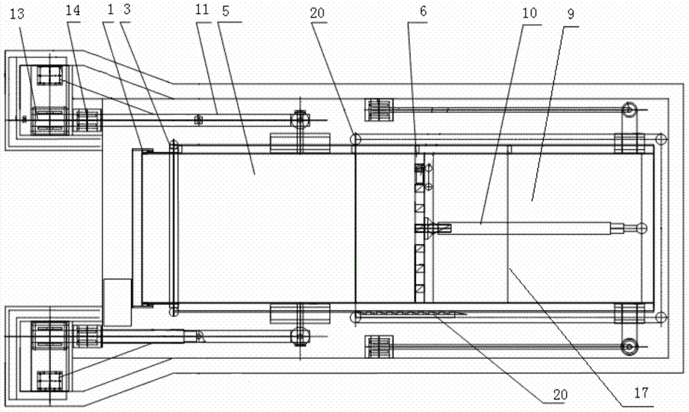
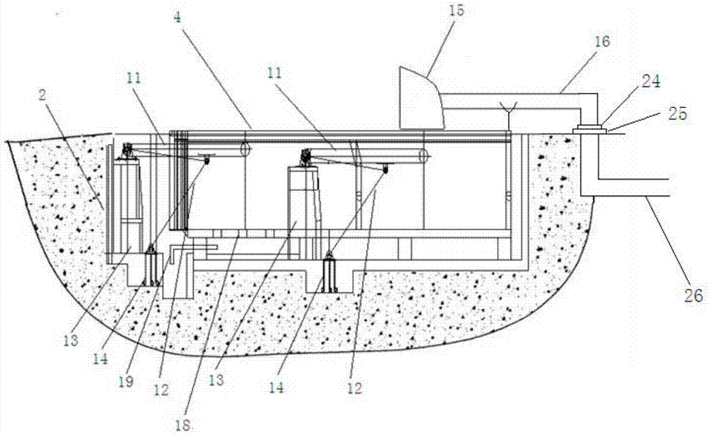
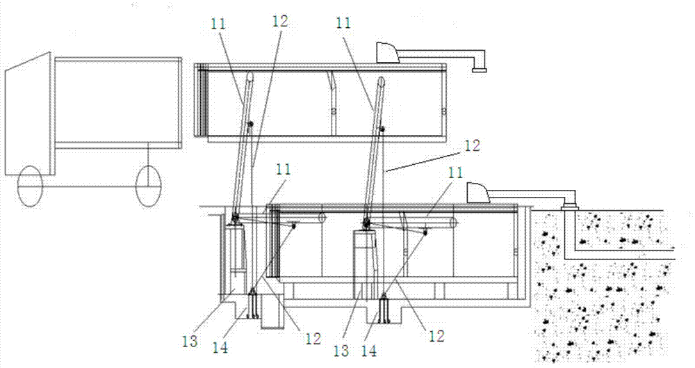
[0032] as attached figure 1 , attached figure 2 As shown, the swing-up type environment-friendly type pit lying garbage compression station of the present embodiment includes the pit 2 and the garbage compression box 4 arranged in the pit 2, the top surface of the garbage compression box 4 is flat with the ground, and the garbage compression The port of the box body 4 is provided with a front door 1 of the pre-press box, and a lifting cylinder 3 for the front door. A pushing plate 6 is arranged behind the front door 4 of the pre-press box, and a compression chamber is formed between the front door 4 and the pushing plate 6 of the pre-press box. 5. The box at the rear of the pusher plate 6 is the pusher cylinder chamber 9, and the middle part of the pusher cylinder chamber 9 is horizontally placed with a multi-stage push cylinder 10, and the pusher plate 6 is hinged on the multi-stage push cylinder 10, the garbage compression box 4 is installed on two groups of lifting mechan...

Embodiment 2

[0036] The structure of this embodiment is the same as that of Embodiment 1, except that the garbage compression box 4 of this embodiment is installed on three groups of lifting mechanisms. When the length of the garbage compression box 4 is longer or the weight of the lift is larger, three groups of lifting mechanisms can provide greater lift to lift the garbage compression box 4 from the pit 2, and the lifting mechanism can also be used according to The weight of the box that needs to be lifted is set in multiple groups, which is flexible and convenient, and the lifting is stable and the lifting weight is large.

Embodiment 3

[0038] as attached Figure 4 , attached Figure 5 , attached Figure 6 , attached Figure 7 As shown, the structure of this embodiment is the same as that of Embodiment 1, the difference is that the pusher plate of this embodiment includes an outer plate 8, an inner plate 7 and an oil cylinder support plate 23, and the outer plate 8, inner plate 7 and oil cylinder support plate 23 Distributed sequentially, a booster pin 22 is arranged between the outer plate 8 and the inner plate 7, and the booster pin 22 is fixed on the inner plate 7, and round holes are distributed on the outer plate 8, and the outer plate 8 is distributed with The position of the round hole matches the position of the booster pin 22 on the inner plate 7, the inner plate 7 is connected to the big end of the multi-stage push cylinder 10, and the cylinder support plate 23 is set behind the inner plate 7 and fixed on the multi-stage On the push cylinder 10 , a booster cylinder 21 is arranged between the inne...


PUM


Abstract

The invention relates to rubbish compression treatment equipment, in particular to a swing lifting type environment-friendly rubbish compression station lying in a pit, which comprises the pit and a rubbish compression box body arranged in the pit. The top surface of the rubbish compression box body is level to the ground, a port of the rubbish compression box body is provided with a pre-pressing box front door and a front door lifting oil cylinder, a material pushing plate is arranged at the back of the pre-pressing box front door, a compression cavity is arranged between the pre-pressing box front door and the material pushing plate, and the rubbish compression box body is installed between two groups of lifting mechanisms. Each lifting mechanism is composed of a lifting swing arm and a swing lifting oil cylinder, the upper end of the lifting swing arm is fixed on the side face of the rubbish compression box body, and the lower end of the lifting swing arm is fixed on a swing arm pedestal installed at the bottom of the pit. The upper end of the swing lifting oil cylinder is connected to the middle of the lifting swing arm, and the lower end of the swing lifting oil cylinder is installed on a pit pedestal embedded part. The swing lifting type environment-friendly rubbish compression station lying in the pit enables passing lifting weight to be huge, lifts smoothly, and is high in rubbish compression treatment efficiency. A multi-stage press push oil cylinder and a pressurizing oil cylinder are combined, and accordingly rubbish compression density is large and compression effect is good.

Description

technical field [0001] The invention and the garbage compression treatment equipment, in particular relate to a swing-up environment-friendly pit garbage compression station. Background technique [0002] With the rapid development of urban construction, urban residents continue to increase, and garbage has soared. The composition of garbage is also constantly changing, and the urban garbage disposal site is getting farther and farther away from the urban area. The original urban garbage removal method is no longer suitable for the development of the city, and the garbage treatment and compression station has emerged as the times require. The present garbage disposal compression station has vertical compression garbage mode and horizontal compression garbage mode. The pressure of vertically compressing garbage is high, the garbage is lumped, and the cost of garbage removal is low, but the equipment is expensive, the cost of housing construction is high, and the environmenta...

Claims


Application Information

Patent Timeline
Patent Type & Authority Patents(China)
IPC IPC(8): B65F9/00
Inventor 蒋诗贵
Owner 德阳旌卫环保工程有限公司
Learn More