Wing of micro ornithopter

A flapper and wing technology, applied in the field of wings, can solve the problems of low aerodynamic efficiency of wings, unreasonable distribution of structural stiffness, poor reliability, etc.

Active Publication Date: 2012-06-20
NORTHWESTERN POLYTECHNICAL UNIV
View PDF10 Cites 5 Cited by
  • Summary
  • Abstract
  • Description
  • Claims
  • Application Information

AI Technical Summary

Problems solved by technology

[0009] In order to overcome the disadvantages of low aerodynamic efficiency, unreasonable structure stiffness distribution and poor reliability in the prior art, the present invention provides a wing of a miniature flapper, which can improve the aerodynamic efficiency of the flapper wing and simplify the wing structure , to improve wing reliability

Method used


Image

  • Wing of micro ornithopter
  • Wing of micro ornithopter
  • Wing of micro ornithopter

Examples


Embodiment 1

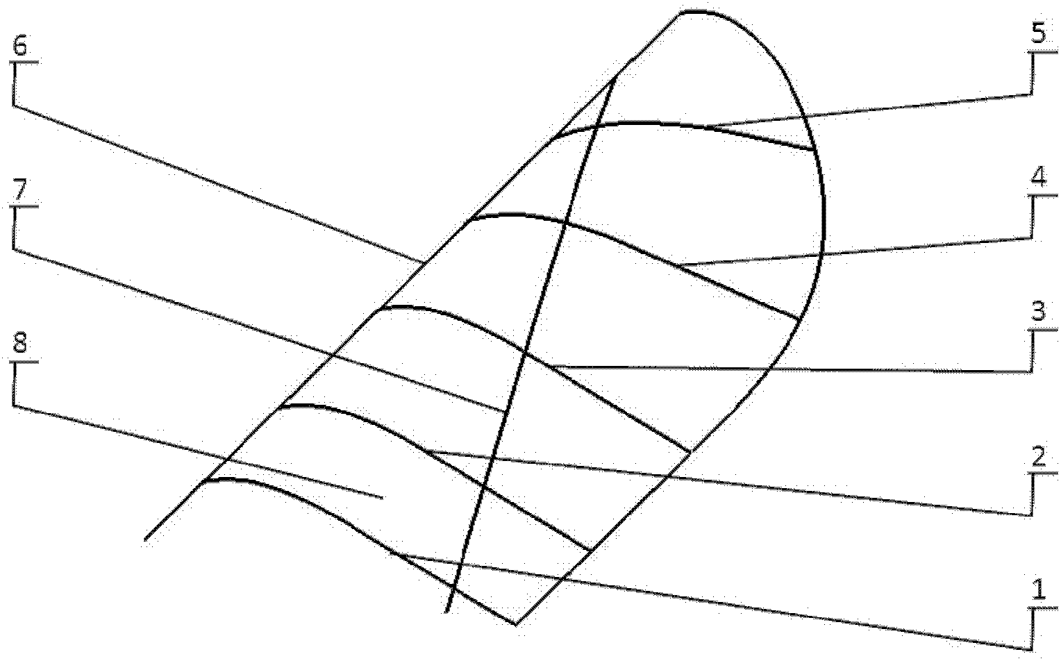
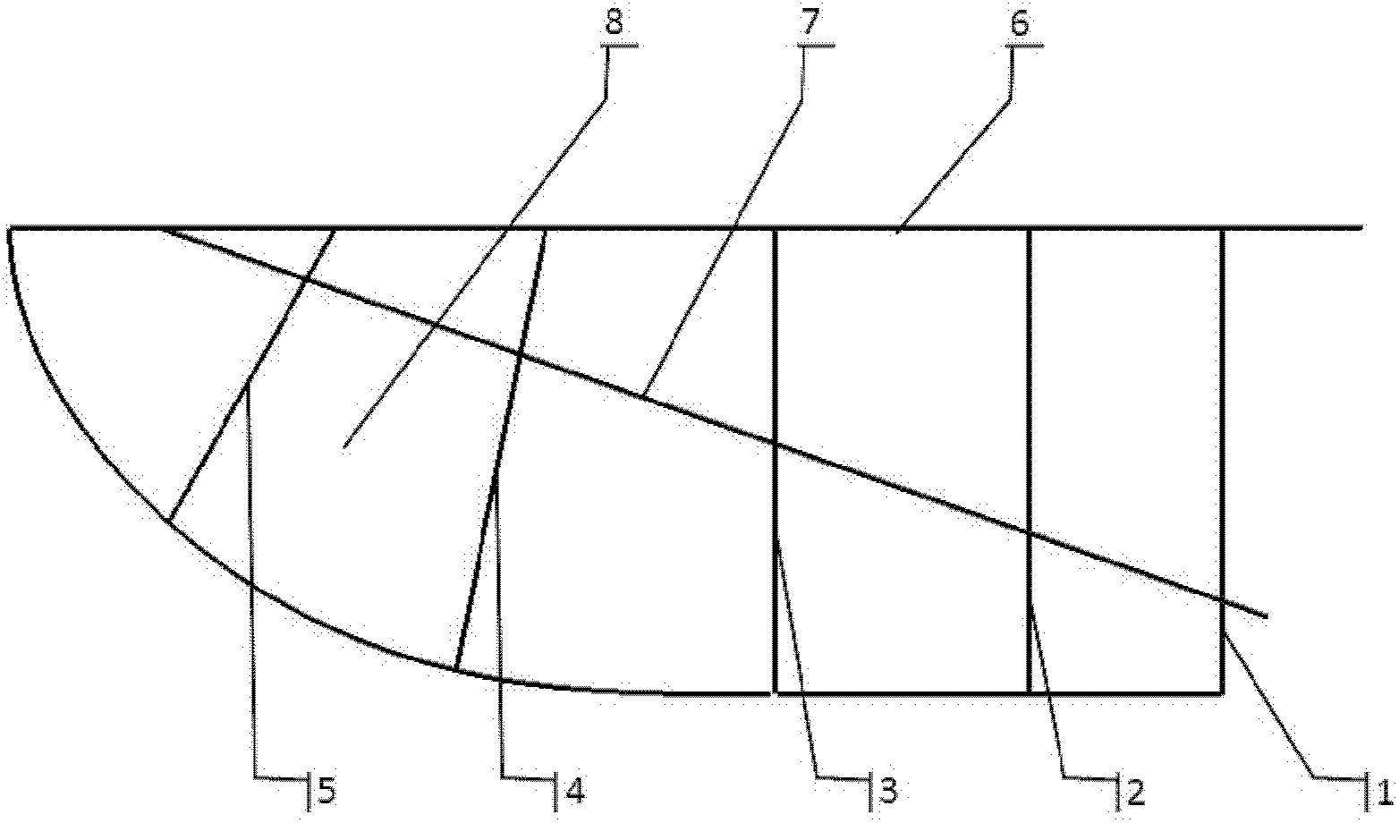
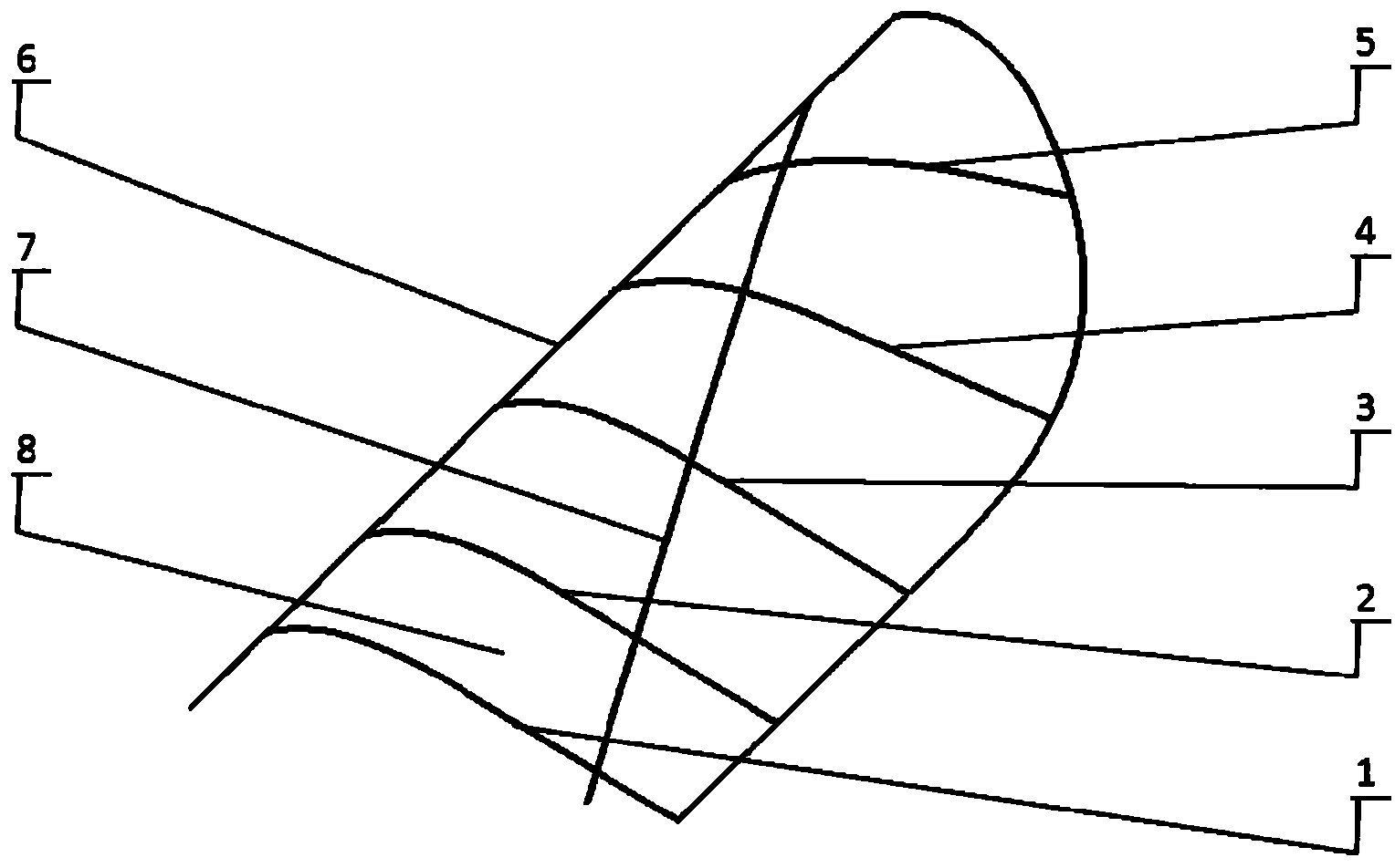
[0027] The present embodiment is that the wing of a pair of miniature flapper aircraft comprises No. 1 rib 1, No. 2 rib 2, No. 3 rib 3, No. 4 rib 4, No. 5 rib 5, main beam 6, auxiliary beam 7, skin 8 .

[0028] Taking the left wing as an example, during implementation:

[0029] No. 1 rib 1, No. 2 rib 2, No. 3 rib 3, No. 4 rib 4, No. 5 rib 5, main beam 6, and auxiliary beam 7 are carbon fiber reinforced resin matrix composite rods, and the aspect ratio is taken as 8, that is The chord length of the No. 1 rib 1 is 25% of the length of the main girder 6 . The main beam 6 is straight, and the front edge points of the five wing ribs 1-5 are fixed on the main beam 6. Starting from the root of the main beam 6, it occupies two-thirds of the spanwise length of the main beam 6. No. 1 ribs 1 and 2 No. 2 rib 2 and No. 3 rib 3 are perpendicular to the main beam, No. 4 rib 4 and No. 5 rib 5 form an acute angle with the direction of the tip of the main beam, and the angles are 70° and 55° ...

Embodiment 2

[0033] The present embodiment is that the wing of a pair of miniature flapper aircraft comprises No. 1 rib 1, No. 2 rib 2, No. 3 rib 3, No. 4 rib 4, No. 5 rib 5, main beam 6, auxiliary beam 7, skin 8 .

[0034]Taking the left wing as an example, during implementation:

[0035] No. 1 rib 1, No. 2 rib 2, No. 3 rib 3, No. 4 rib 4, No. 5 rib 5, main beam 6, and auxiliary beam 7 are carbon fiber reinforced resin matrix composite rods, and the aspect ratio is taken as 6, that is The chord length of the No. 1 rib 1 is 33% of the length of the main girder 6 . The main beam 6 is straight, and the front edge points of the five wing ribs 1-5 are fixed on the main beam 6. Starting from the root of the main beam 6, it occupies 4 / 5 of the spanwise length of the main beam 6. No. 1 ribs 1 and 2 No. 2 rib 2 and No. 3 rib 3 are perpendicular to the main beam, No. 4 rib 4 and No. 5 rib 5 form an acute angle with the direction of the tip of the main beam, and the angles are 80° and 65° respecti...

Embodiment 3

[0039] The present embodiment is that the wing of a pair of miniature flapper aircraft comprises No. 1 rib 1, No. 2 rib 2, No. 3 rib 3, No. 4 rib 4, No. 5 rib 5, main beam 6, auxiliary beam 7, skin 8 .

[0040] Taking the left wing as an example, during implementation:

[0041] No. 1 rib 1, No. 2 rib 2, No. 3 rib 3, No. 4 rib 4, No. 5 rib 5, main beam 6, and auxiliary beam 7 are carbon fiber reinforced resin matrix composite rods, and the aspect ratio is taken as 7, that is The chord length of the No. 1 rib 1 is 28% of the length of the main girder 6 . The main beam 6 is straight, and the front edge points of the five wing ribs 1-5 are fixed on the main beam 6. Starting from the root of the main beam 6, it occupies 73% of the spanwise length of the main beam 6. No. 1 ribs 1 and No. 2 ribs No. 2 and No. 3 ribs 3 are perpendicular to the main beam, No. 4 ribs 4 and No. 5 ribs 5 form an acute angle with the direction of the tip of the main beam, and the angles are 78° and 63° r...


PUM


Abstract

The invention discloses a wing of a micro ornithopter. According to the present invention, a main beam is level and straight; the front edge points of five wing ribs are fixed on the main beam; the wing rib No.1, the wing rib No.2 and the wing rib No.3 are perpendicular to the main beam; the wing rib No.4 and the wing rib No.5 form acute angles with the tip part direction of the main beam; the chord lengths of the wing rib No.1, the wing rib No.2 and the wing rib No.3 are the same; the chord length of wing rib No.4 and the chord length of the wing rib No.5 are sequentially reduced, and are shorter than the chord length of the wing rib No.1; an assistant beam is an arc structure; the outer edge point of the assistant beam is fixed on the main beam between the end point of the tip part of the main beam and the rear edge point of the wing rib No.5, the root part of the assistant beam passes through the rear half part of the wing rib No.1, the assistant beam contacts the positions corresponding to the five wing ribs and is fixed with the positions corresponding to the five wing ribs; the main beam, the assistant beam and the wing ribs form a wing structure frame, and a skin is adhered above the frame to form a complete wing. With the present invention, the stiffness distribution of the whole wing flatly transits, the structure continuity is good, the good force loading property is provided, the structure is simple, and the wing of the present invention is convenient to manufacture.

Description

technical field [0001] The invention relates to a wing, in particular to a wing of an orthopter. Background technique [0002] The micro flapping wing aircraft is a new concept aircraft that imitates the flight of birds. It has the advantages of small size, light weight, good concealment, flexible use, and high efficiency. If it is equipped with sensors and related data transmission and flight control systems, it will form a miniature The flapping wing UAV platform will have broad application prospects. Around this subject, various countries have developed controllable flapping-wing aircraft, among which the more successful ones are the “Microbat” jointly developed by Aero Vironment of the United States and the University of California, and the “Delfly” developed by Delft University in the Netherlands. There is still a big gap, which is mainly reflected in the limited flight time, small payload, and difficult control. Trace it to its cause, the low aerodynamic efficiency o...

Claims


Application Information

Patent Timeline
Patent Type & Authority Applications(China)
IPC IPC(8): B64C33/02
Inventor 宋笔锋王利光樊邦奎鲁合营杨文青李洋付鹏王进
Owner NORTHWESTERN POLYTECHNICAL UNIV
Why Eureka
Try Eureka