Iron core structure of motor

A technology of iron core and structure, applied in the manufacture of stator/rotor body, magnetic circuit shape/style/structure, salient poles, etc., can solve the problems of insufficient mechanical strength of the iron core, and achieve the effect of high strength and rigidity

Inactive Publication Date: 2012-06-20
多摩川精密电机(苏州)有限公司
View PDF5 Cites 1 Cited by
  • Summary
  • Abstract
  • Description
  • Claims
  • Application Information

AI Technical Summary

Problems solved by technology

In other words, because the insulating material is only embedded in the teeth of the iron core and is not fixed, it is only fixed with a sealant on the

Method used


Image

  • Iron core structure of motor
  • Iron core structure of motor
  • Iron core structure of motor

Examples


Embodiment Construction

[0019] Hereinafter, an embodiment of a suitable motor core structure according to the present invention will be described with reference to the drawings.

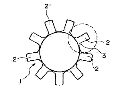
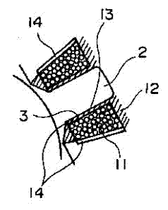
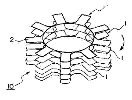
[0020] figure 1 It is a stamped wheel-shaped iron sheet 1, which is formed by a plurality of outwardly facing tooth portions 2. On the side of the tooth portion 2 of the above-mentioned core sheet 1, such as figure 2 The undercut 3 is shown formed. Such as image 3 As shown, a plurality of iron chips 1 are rotated and superimposed from the tooth portion 2 in the axial direction, that is, the commonly referred to as a rotation superimposed structure, thus forming a structure such as Figure 4 Iron cores 10 of a given thickness are stacked in turns as shown.

[0021] The above iron core 10 is in Figure 4 Coil 11 etc. are not set in, in fact it is as figure 2 As shown, the coil 11 of the insulating material 12 is coated on the periphery of the tooth portion 2 , so that a gap 13 is formed between the insulating materia...


PUM


Abstract

The invention enables a sealing agent such as resin to be filled in gaps of a tooth portion and an insulating material so as to improve strength of iron core sheets. An iron core structure includes that when a plurality of iron core sheets rotate, the sealing agent such as the resin is filled in the gaps formed by the tooth portion and the insulating material and hardened so as to enhance the strength of an iron core and fix the insulating material and coils.

Description

technical field [0001] The present invention relates to the structure of the motor core, especially the gap formed between the teeth of the laminated core and the insulating material by injecting a sealant to harden it, in order to increase the mutual bonding strength between the coil and the insulating material and the core. improved. Background technique [0002] The motor core structure used in the past is generally formed by placing a coil between insulating materials on the teeth of the laminated core, and coating the outer surface of the coil with a resin sealant or the like. [0003] The conventional motor core structure has the following problems because it is constructed based on the above-mentioned principle. In other words, because the insulating material is only embedded in the teeth of the iron core and is not fixed, it is only fixed with a sealant on the outside of the coil, the insulating material and the iron core are not fixed together, and the mechanical s...

Claims


Application Information

Patent Timeline
IPC IPC(8): H02K1/08H02K15/02
Inventor 细泽和司
Owner 多摩川精密电机(苏州)有限公司
Why Eureka
Try Eureka