Structure for suppressing flow vibration of instrumentation guide tube

一种计量仪器、振动抑制的技术,应用在流动振动抑制构造领域,能够解决磨损等问题

Inactive Publication Date: 2012-06-27
MITSUBISHI HEAVY IND LTD
View PDF7 Cites 0 Cited by
  • Summary
  • Abstract
  • Description
  • Claims
  • Application Information

AI Technical Summary

Problems solved by technology

Therefore, the gauge pipe 1 may be repeatedly contacted with the upper core support column 4 and the structure of the core 5, resulting in abrasion.

Method used


Image

  • Structure for suppressing flow vibration of instrumentation guide tube
  • Structure for suppressing flow vibration of instrumentation guide tube
  • Structure for suppressing flow vibration of instrumentation guide tube

Examples


Embodiment Construction

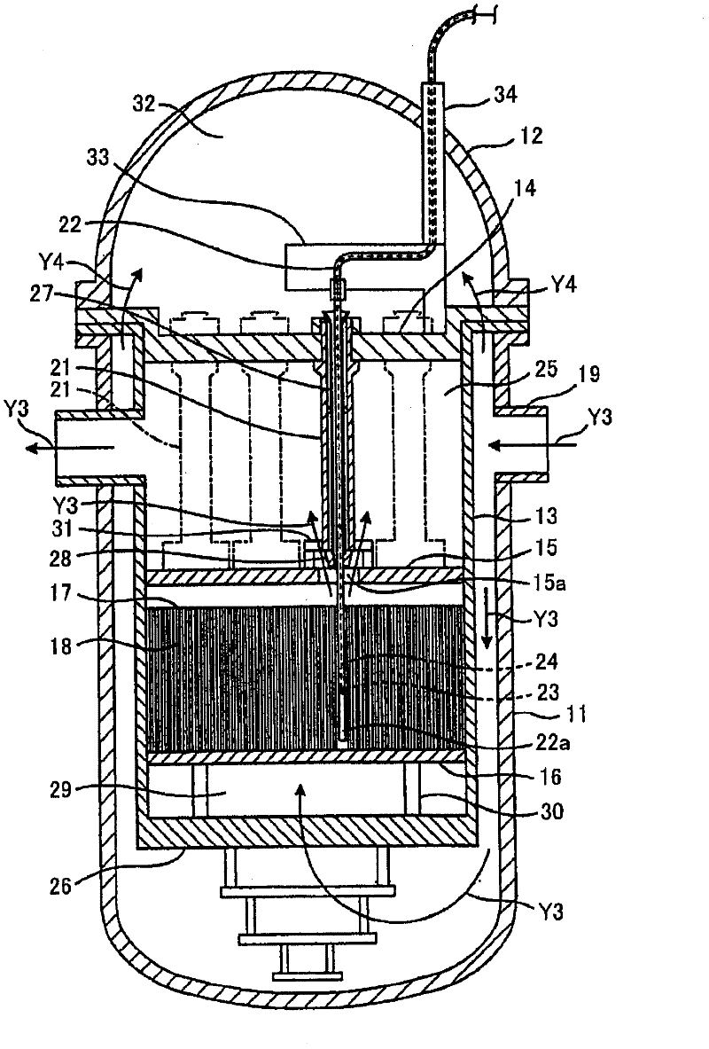
[0271]Hereinafter, embodiments of the present invention will be described in detail with reference to the drawings. The present invention is suitable for a PWR (pressurized water reactor) type reactor, but the application target of the present invention is not limited thereto, and the present invention can also be applied to a BWR (boiling water reactor) type reactor.

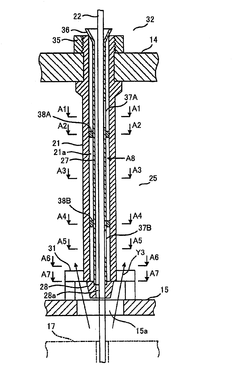
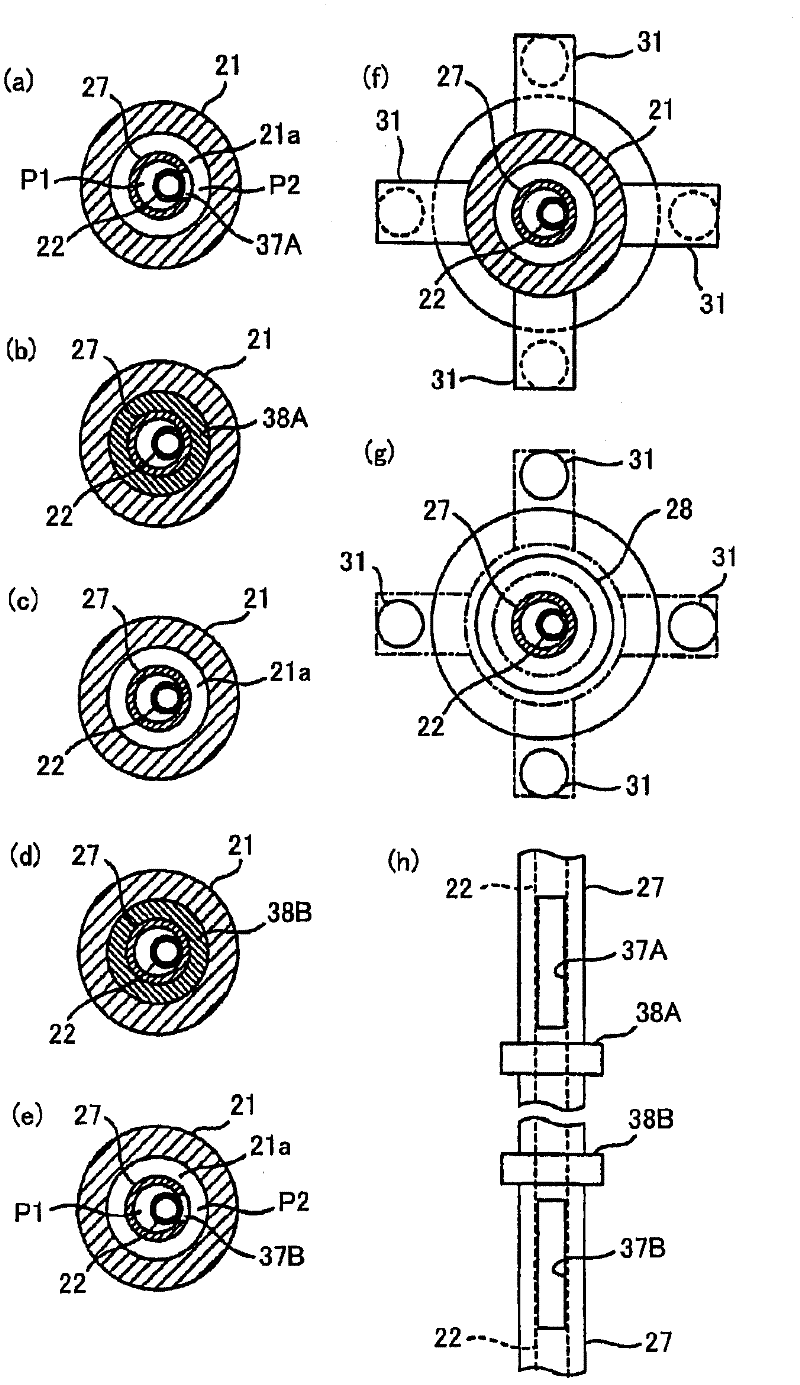
[0272] figure 1 It is a schematic cross-sectional view showing the internal structure of a PWR reactor vessel equipped with a flow vibration suppression structure of a gauge conduit according to a first embodiment of the present invention, figure 2 From figure 1 An enlarged cross-sectional view showing the flow vibration suppressing structure of the above-mentioned measuring instrument conduit extracted. in addition, image 3 (a) is figure 2 The A1-A1 line arrow observes the enlarged view of the section, image 3 (b) is figure 2 The A2-A2 line arrow observes the enlarged view of the section, image...


PUM


Abstract

The invention provides a structure for suppressing flow vibration of an instrumentation guide tube, comprising a tube configured to be in a hollow upper core support column between an upper core supporting plate and an upper core plate in a reactor vessel; and a front end nozzle configured to be at a lower end of the upper core support column, wherein the lower end part of the instrumentation guide tube is from up to down successively goes into the tube, the front end nozzle and an opening part on the upper core plate to be inserted into the core, wherein the at least a lower part of the tube side is provided with a lower part hole; the instrumentation guide tube is pressed on an inner circle surface by the pressure difference between the inner side of the lower part hole and the cooling materials on the outer side.

Description

[0001] This application is a divisional application, the application number of its parent application is: 200880005834.4, the application date: 2008.02.22, the name of the invention: the flow vibration suppression structure of the measuring instrument conduit. technical field [0002] The present invention relates to a flow vibration suppressing structure of a gauge conduit inserted into a core. Background technique [0003] When a neutron detector is installed in the core of a pressurized water reactor (PWR), the detector is guided into the core through a gauge guide inserted into the core. In addition, as a method of inserting the gauge conduit into the core, the bottom insertion method of inserting the gauge conduit from the bottom to the top of the reactor vessel has been used previously, but in the current technology, the method of inserting the gauge conduit from the top of the reactor vessel to the top is being considered. An upper insertion method that inserts the ga...

Claims


Application Information

Patent Timeline
Patent Type & Authority Applications(China)
IPC IPC(8): G21C17/10
CPCG21Y2002/303G21Y2004/30G21C3/322G21Y2002/207Y02E30/32G21C17/10G21C17/08Y02E30/30
Inventor 宇多信喜渡边茂行广田和生坂田英之森田英之中岛诚栗村力市川利郎
Owner MITSUBISHI HEAVY IND LTD
Why Eureka
Try Eureka