Driving mechanism of particle crusher

A transmission mechanism and shredder technology, applied in grain processing and other directions, can solve the problems of difficulty in ensuring the roller spacing, small range of gear pairs, and small adjustable range, so as to reduce the frequency of replacing rollers, achieve uniform synchronization and precise adjustment, and expand The effect of adjusting the range

Inactive Publication Date: 2012-07-04
JIANGSU MUYANG GRP CO LTD
View PDF10 Cites 16 Cited by
  • Summary
  • Abstract
  • Description
  • Claims
  • Application Information

AI Technical Summary

Problems solved by technology

[0004] 1. When adjusting the spacing of the crushing rollers, the center distance of the meshing gears will change accordingly, and the gear pair will be in an abnormal meshing state for a long time, and even disengage during operation, resulting in tooth beating, which is very easy to damage the gears
[0005] 2. Due to the small adjustable range of the center distance of the gear pair, the adjustable range of the distance between the fast roller and the slow roller is also very small
In this way, when the rollers are worn or trimmed after being used for a period of time, the distance between the rollers increases, and it is difficult to ensure the normal crushing roller distance by adjusting the distance between the gears. In order to ensure the crushing effect, the only way to replace the rollers is to cause great waste
[0006] 3. The spacing between the rollers is adjusted separately through the adjustment mechanisms at both ends of the slow rollers. It is difficult to control the uniformity and dimensional accuracy of the spacing, and the labor intensity is high and the adjustment efficiency is low.

Method used


Image

  • Driving mechanism of particle crusher
  • Driving mechanism of particle crusher
  • Driving mechanism of particle crusher

Examples


Embodiment Construction

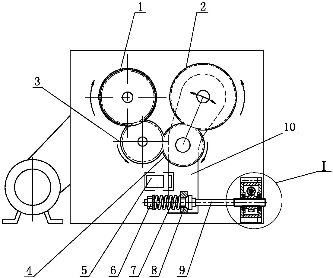
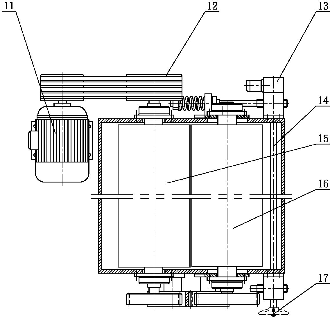
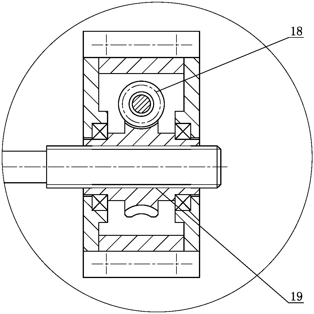
[0018] Such as figure 1 Shown in -3 is the granulator transmission mechanism of the present invention, comprising fast roller 15, slow roller 16, idler gear I3 and idler gear II4, and the shaft end of quick roller 15 one side is equipped with belt pulley 12, and by belt driving device and The motor 11 is connected, the driving gear 1 is installed on the other side of the fast roller 15, the slow roller driving gear 2 is installed on the same side of the slow roller 16, the idler gear I3 meshes with the driving gear 1 and the idler gear II respectively 4, and the idler gear I Gear Ⅱ4 meshes with the slow roller drive gear 2, and the shaft ends on both sides of the slow roller 16 are provided with a pair of support plates 10 for adjusting the distance between the fast roller 15 and the slow roller 16, and the slow roller 16 supports the support plates 10 installed on both sides Above, the two pairs of support plates 10 drive the slow roller 16 and the slow roller drive gear 2 to...


PUM


Abstract

The invention relates to a driving mechanism of a particle crusher. The driving mechanism of the particle crusher comprises a quick roller, a slow roller, an idle gear I and an idle gear II, wherein a driving gear is arranged on an axial end on one side of the quick roller; a slow roller driving gear is arranged on the axial end on the same side of the slow roller; two pair of supporting plates are respectively arranged on the axial ends on the two sides of the slow roller; the two pairs of supporting plates synchronously swing through the driving of a synchronous adjusting mechanism, so the distance between the quick roller and the slow roller is synchronously and uniformly adjusted; the synchronous adjusting mechanism comprises two groups of turbine worm pairs and screw rod nut pairs; the nuts of each group of screw rod nut pairs are turbines of the turbine worm pairs; each group of screw rods is axially and fixedly connected with an adjusting rod; the adjusting rod is connected with a supporting plate; a spring which elastically resets the supporting plate is arranged between the adjusting rod and the supporting plate; and the two groups of worms are coaxially connected througha driving shaft to realize synchronous rotation. Due to the adoption of the driving mechanism of the particle crusher, when the distance between the rollers is adjusted, a gear driving system is always in an optimal meshing state, the distance between the quick roller and the slow roller is synchronously adjusted precisely, the frequency of replacing the rollers is reduced, and the application range of the particle crusher is widened.

Description

technical field [0001] The invention relates to a granulator device, in particular to a granulator transmission mechanism. Background technique [0002] The transmission mode of the existing granulator is that the motor drives the fast roller to rotate through the belt drive, and the fast roller drives the slow roller to rotate through the gear transmission system, so as to realize the opposite rotation of the fast roller and the slow roller, so as to achieve the purpose of crushing the material, and the slow roller is opposite to each other. The position of the fast roller can be adjusted to realize the function of adjusting the distance between the rollers. The adjustment of the distance between the rollers is realized by adjusting the positions of the two ends of the slow rollers respectively, and the size and uniformity of the adjustment distance are determined by visual inspection. When the work is overloaded or there are large particles of hard impurities in the proce...

Claims


Application Information

Patent Timeline
Patent Type & Authority Applications(China)
IPC IPC(8): B02C4/32
Inventor 闾宏
Owner JIANGSU MUYANG GRP CO LTD
Why Eureka
Try Eureka