
Pressure reducing valve structure and method for adjusting gas pressure

A gas pressure and pressure reducing valve technology, applied in safety valves, balance valves, valve devices, etc., can solve the problems of complex pressure regulation process, long time, and inability to stabilize the outlet pressure within a certain range.

Active Publication Date: 2012-07-04
PARKER HANNIFIN POWER TRANSMISSION PROD WUXICO LTD
View PDF5 Cites 8 Cited by
  • Summary
  • Abstract
  • Description
  • Claims
  • Application Information

AI Technical Summary

Problems solved by technology

[0002] The existing pressure reducing valve structure for regulating gas pressure is generally a manual pressure regulating device. When a certain value of gas pressure needs to be output, manual adjustment is required to obtain the required pressure after decompression. The pressure regulating process is complicated and takes a long time. , when the pressure is adjusted to a certain pressure value, the corresponding cut-off port is in a fixed state; when the inlet pressure changes, the outlet pressure will also change accordingly, and the outlet pressure cannot be stabilized within a certain range

Method used


Image

  • Pressure reducing valve structure and method for adjusting gas pressure
  • Pressure reducing valve structure and method for adjusting gas pressure
  • Pressure reducing valve structure and method for adjusting gas pressure

Examples


Embodiment Construction

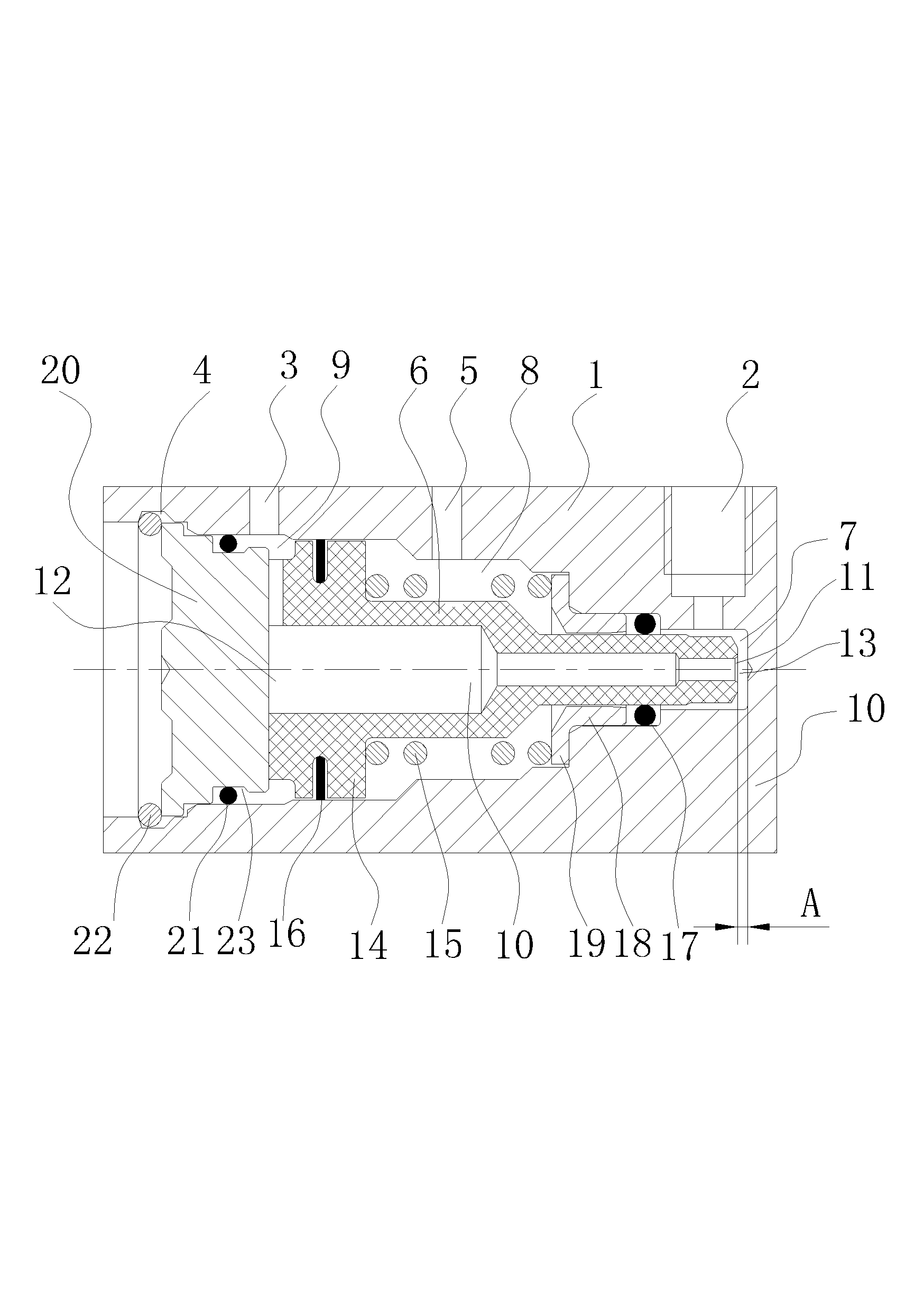
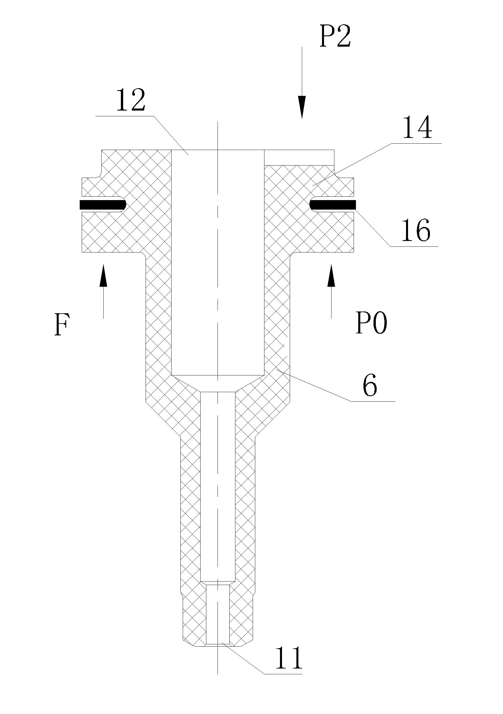
[0015] A pressure reducing valve structure for regulating gas pressure, see figure 1 : It includes the pressure input port 2, the pressure output port 3 and the end sealing plug of the valve core body 1, the end sealing plug is located on the side of the pressure output port 3 of the valve core body 1, and the middle part of the valve core body 1 has an atmospheric communication port 5. There is a pressure balance shaft 6 inside the valve core body 1, and the inner wall of the valve core body 1 cooperates with the outer edge surface of the pressure balance shaft 6 and the inner wall of the end sealing plug respectively to form a pressure input chamber 7, an atmosphere communication chamber 8, and a pressure The output cavity 9, the three cavities are sealed and isolated by seals, the pressure input port 2, the atmospheric communication port 5, and the pressure output port 3 are respectively connected to the pressure input cavity 7, the atmospheric communication cavity 8, the pr...


PUM

PropertyMeasurementUnit
Sizeaaaaaaaaaa

Abstract

The invention provides a pressure reducing valve structure for adjusting gas pressure. A pressure adjustment process is simple, and the pressure adjustment time is short; and furthermore, when the gas inlet pressure is changed, the gas outlet pressure can be stabilized in a certain range. The pressure reducing valve structure comprises a pressure input port, a pressure output port and an end sealing plug of a valve core body, wherein the end sealing plug is positioned on one side of the pressure output port of the valve core body. The pressure reducing valve structure is characterized in that: an atmosphere communicating port is formed in the middle of the valve core body; a pressure balance shaft is arranged inside the valve core body; the inner wall of the valve core body is matched with the outer rim surface of the pressure balance shaft and the inner wall of the end sealing plug respectively to form a pressure input cavity, an atmosphere communicating cavity and a pressure output cavity; the three cavities are sealed and isolated through sealing pieces; the pressure input port, the atmosphere communicating port and the pressure output port are correspondingly communicated with the pressure input cavity, the atmosphere communicating cavity and the pressure output cavity; a throughout flow channel is arranged in the pressure balance shaft; and one end of the flow channel is provided with a gas inlet hole, and the other end of the flow channel is provided with a gas outlet hole.

Description

technical field [0001] The invention relates to the technical field of gas pressure adjustment, in particular to a pressure reducing valve structure for adjusting gas pressure, and the invention also provides a method for adjusting gas pressure. Background technique [0002] The existing pressure reducing valve structure for regulating gas pressure is generally a manual pressure regulating device. When a certain value of gas pressure needs to be output, manual adjustment is required to obtain the required pressure after decompression. The pressure regulating process is complicated and takes a long time. , when the pressure is adjusted to a certain pressure value, the corresponding orifice is in a fixed state; when the inlet pressure changes, the outlet pressure will also change accordingly, which cannot stabilize the outlet pressure within a certain range. Contents of the invention [0003] In view of the above problems, the present invention provides a pressure reduci...

Claims


Application Information

Patent Timeline
IPC IPC(8): F16K17/00
Inventor 潘艺园陈荣彬
Owner PARKER HANNIFIN POWER TRANSMISSION PROD WUXICO LTD
Learn More