Bracket assembly and miniature image pick-up device

A technology of camera devices and components, which is applied in the directions of machines/brackets, supporting machines, electrical components, etc., can solve the problems of camera working angle deviation, position deviation, and narrow camera angle adjustment range, so as to improve the angle adjustment range, Avoid offset effects

Active Publication Date: 2012-07-04
HANGZHOU HIKVISION DIGITAL TECH
View PDF7 Cites 9 Cited by
  • Summary
  • Abstract
  • Description
  • Claims
  • Application Information

AI Technical Summary

Problems solved by technology

[0005] The angle adjustment range of the existing cameras that rotate in the horizontal and vertical directions is narrow, and the connection structure between the pan-tilt assembly and the base assembly

Method used


Image

  • Bracket assembly and miniature image pick-up device
  • Bracket assembly and miniature image pick-up device
  • Bracket assembly and miniature image pick-up device

Examples


Example Embodiment

[0061] In order to make the objectives, technical solutions, and advantages of the present invention clearer and more comprehensible, the following further describes the present invention in detail with reference to the accompanying drawings and embodiments.

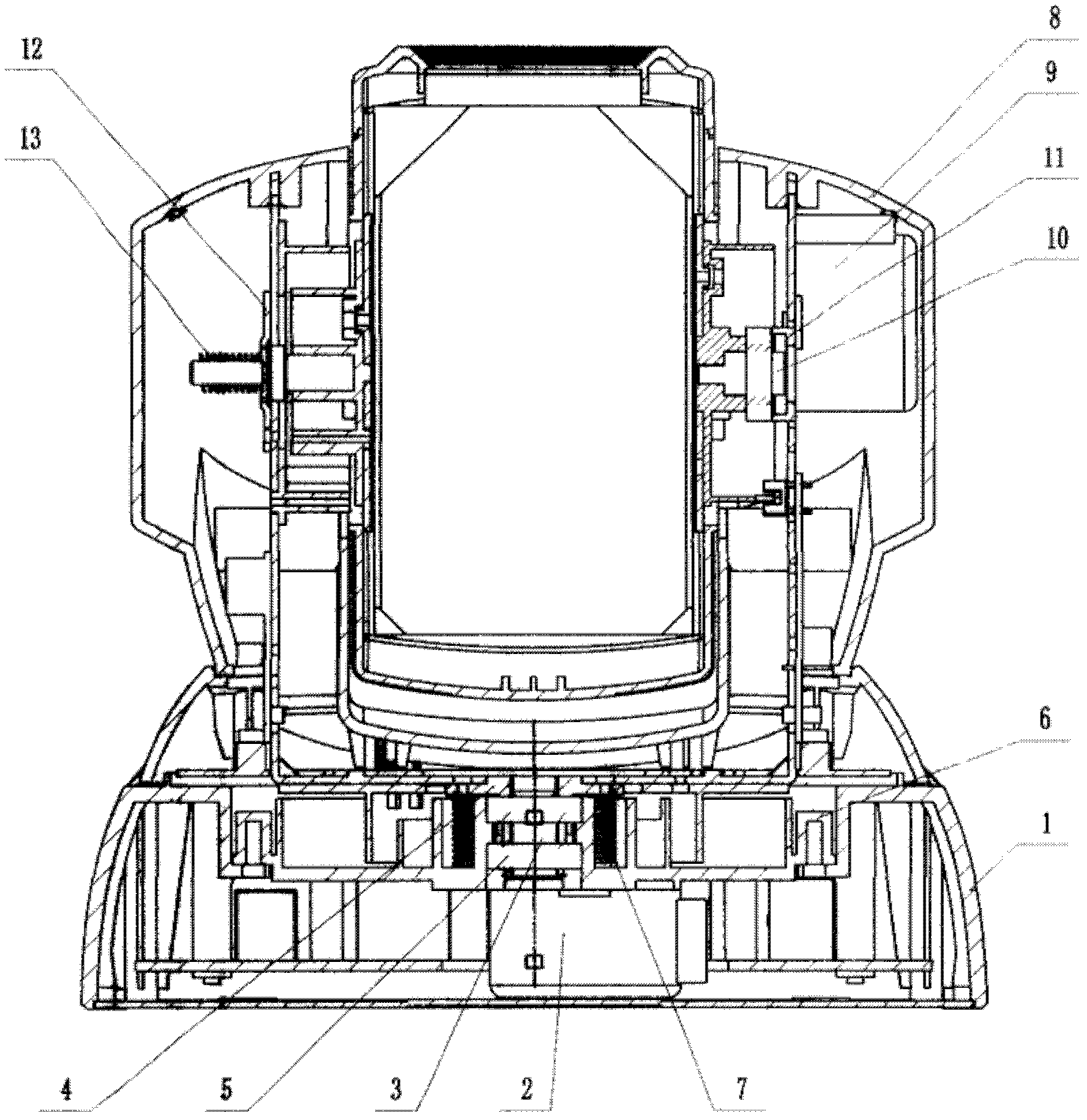
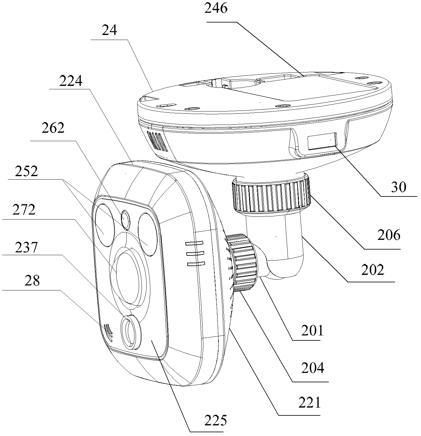
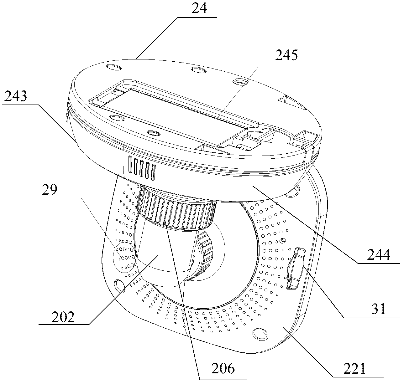
[0062] figure 2 This is the front view of the miniature camera of the present invention. image 3 This is the right side view of the micro camera device of the present invention. Figure 4 It is a three-dimensional exploded schematic diagram of the micro camera device of the present invention. Figure 5 This is a cross-sectional view of the micro camera device of the present invention. Figures 6(a)-(b) are schematic diagrams of the rotation of the micro camera device of the present invention. Now combined Figure 2 to Figure 6(b) , The micro-camera device of the present invention will be described, specifically as follows:

[0063] The miniature camera device of the present invention includes: a bracket assembly 20, a front...


PUM


Abstract

The invention provides a bracket assembly, which comprises a first bracket, a second bracket, at least one first gasket and a first compression nut, wherein one end of the first bracket extends into a front-end assembly, and the other end of the first bracket is connected to one end of the second bracket; a pedestal assembly extends into the other end of the second bracket; one end of the first gasket is wedged into a gap between the part of the first bracket extending into the front-end assembly and the front-end assembly, and the other end of the first gasket is embedded into the inner surface of the first compression nut; and the first compression nut is annularly sleeved on the outer surfaces of the first bracket and the front-end assembly in which the first bracket extends, the first gasket is driven to be screwed into the gap between the part of the first bracket extending into the front-end assembly and the front-end assembly towards a direction near the front-end assembly when the first compression nut is stressed to rotate towards the direction near the front-end assembly; and the front-end assembly is locked in the gap which is formed by the front-end assembly and the first gasket. The invention also provides a miniature image pick-up device which is provided with the bracket assembly. By adopting the bracket assembly and the image pick-up device disclosed by the invention, the angle-regulating range can be enlarged, the deviation occurring at a position in a vibrating environment is avoided.

Description

Technical field [0001] The invention relates to video monitoring technology, in particular to a bracket assembly and a miniature camera device. Background technique [0002] figure 1 It is a schematic diagram of an existing assembly structure of a camera that rotates horizontally and vertically. Now combined figure 1 , To describe the existing cameras that rotate horizontally and vertically, as follows: [0003] The existing camera that rotates in the horizontal and vertical directions mainly consists of a camera assembly, a pan-tilt assembly and a base assembly. The base assembly is mainly composed of base 1, horizontal motor 2, cross coupling 3, main shaft 4, horizontal bearing 5, horizontal bearing seat 6 and horizontal spring 7. The output shaft of horizontal motor 2 is connected to main shaft 4 through cross coupling 3 Connection, the main shaft 4 is connected with the pan / tilt assembly, the horizontal bearing seat 6 is located on the base 1, the horizontal bearing 5 is arra...

Claims


Application Information

Patent Timeline
IPC IPC(8): F16M11/12F16M11/18G03B17/56H04N5/225
Inventor 颜财盛应亮应向群叶展
Owner HANGZHOU HIKVISION DIGITAL TECH
Why Eureka
Try Eureka