
Image collecting device for precisely aligning and image collecting assembly thereof

An image acquisition and component technology, applied in the direction of using optical devices, measuring devices, instruments, etc., can solve the problems such as the inability to obtain due compensation for spatial errors, the great impact on the final alignment accuracy, and the reduction of alignment accuracy. The effect of shortening time, improving operation convenience, and reducing relative error

Active Publication Date: 2014-05-28
METAL INDS RES & DEV CENT
View PDF3 Cites 0 Cited by
  • Summary
  • Abstract
  • Description
  • Claims
  • Application Information

AI Technical Summary

Problems solved by technology

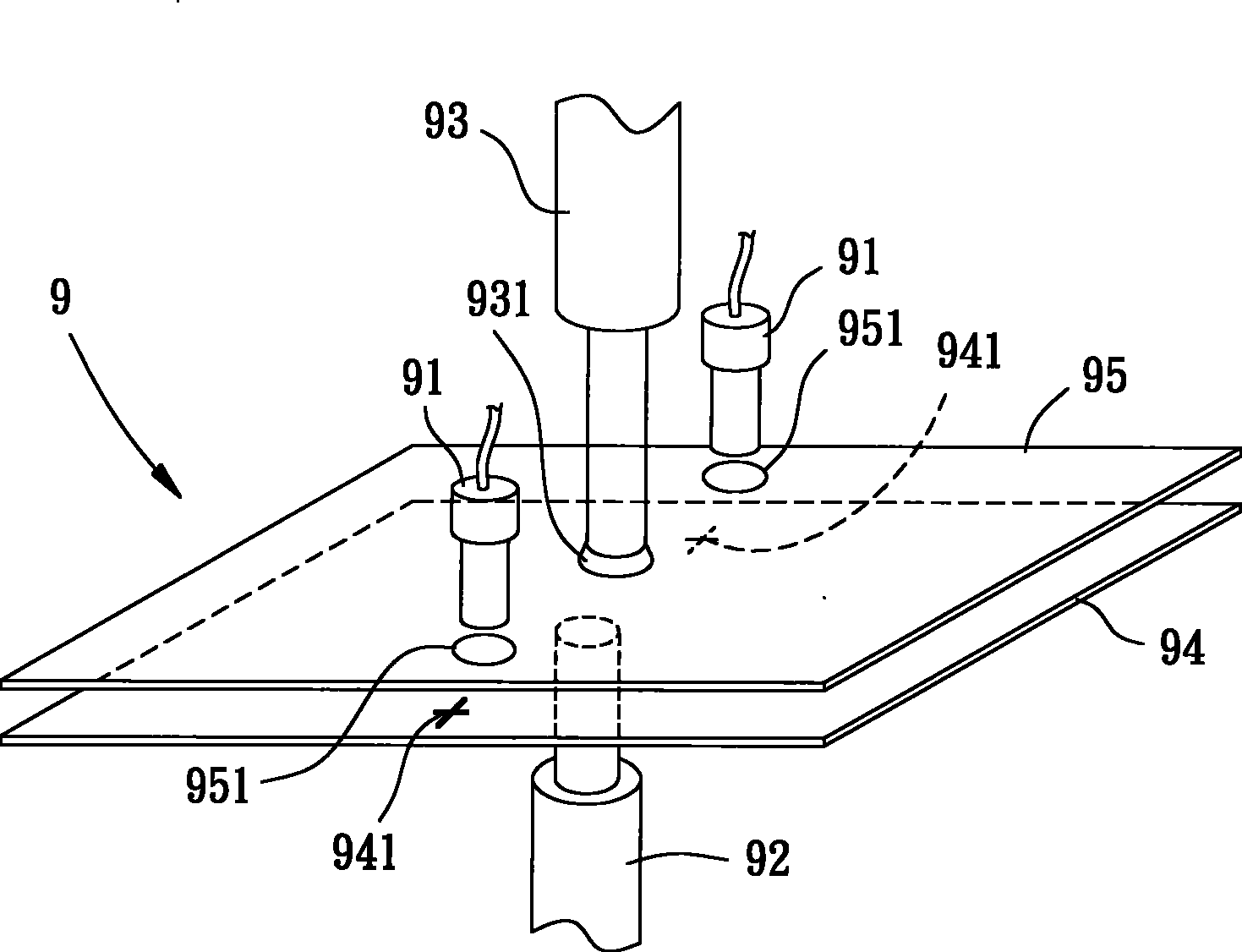
[0009] However, since the image acquisition alignment device 8 is to wait for the spatial error compensation and adjustment of the upper and lower objects 85 and 84, and then rotate the upper object 85 by 180 degrees, it is often easy to make the upper and lower objects 85 , 84 additional rotation errors are generated during the rotation process, which reduces the alignment accuracy
[0010] Furthermore, since the precise relative positions of several image acquisition components 81 erected by the image acquisition and alignment device 8 have a great influence on the final alignment accuracy, if the correction is not good or the locking pieces are loose and collided, the image acquisition components 81 will be damaged. The positional deviation will cause relative errors between the image acquisition components 81 and affect the entire image acquisition alignment device 8, resulting in that the spatial error between the upper and lower objects 85, 84 cannot be properly compensated. And reduce the alignment accuracy between the upper and lower objects 85,84

Method used


Image

  • Image collecting device for precisely aligning and image collecting assembly thereof
  • Image collecting device for precisely aligning and image collecting assembly thereof
  • Image collecting device for precisely aligning and image collecting assembly thereof

Examples


Embodiment Construction

[0051] In order to make the above-mentioned and other objects, features and advantages of the present invention more comprehensible, the preferred embodiments of the present invention are specifically cited below, together with the accompanying drawings, as follows:

[0052] Please refer to Figure 4 As shown, the image acquisition device for precise alignment according to the first embodiment of the present invention includes an image acquisition assembly 1, a carrying platform 2 and a carrier 3, and the carrier 3 is displaced relative to the carrying platform 2 for To align the carrying platform 2 , and when the image is captured, the image capturing component 1 is located between the carrying platform 2 and the carrier 3 .

[0053] The image acquisition assembly 1 has several light guide assemblies 11 and two image pickup assemblies 12, 12'. In this embodiment, each image pickup assembly includes a charge coupled device (Charge Coupled Device, CCD) and a lens. The componen...


PUM


Abstract

The invention provides an image collecting device for precisely aligning, comprising a vehicle and an image collecting assembly, wherein the carrier is used for aligning a bearing platform; the image collecting assembly comprises a light guide assembly and two image capturing assemblies; a light transmission path is respectively arranged between each one of the two image capturing assemblies and the light guide assembly; the light guide assembly is provided with a plurality of light inputting sides and a plurality of light outputting sides; the light guide assembly further comprises two reflective prisms and the two reflective prisms are respectively provided with reflective surfaces; when the image collecting assembly is located at one image capturing position, the light inputting sides are respectively placed towards the bearing platform and the vehicle and the light outputting sides are respectively placed towards the image capturing assemblies; lights of the bearing platform and the vehicle are respectively emitted into the two reflective prisms through the light inputting sides; and the lights reflected by the reflective surfaces of the two reflective prisms are respectively output to the two image capturing assemblies through the light outputting sides along the light transmission paths.

Description

technical field [0001] The invention relates to an image acquisition device capable of simultaneously acquiring bilateral images, in particular to an intrusive image acquisition device for precise alignment of two objects. Background technique [0002] The application range of double-object or double-layer board alignment technology is very wide. For example, semiconductors, flat-panel displays, printed circuit boards and other fields need to implement double-object or double-layer board alignment technology. Therefore, major industries have adopted double-object Or the double-layer board alignment technology is improved, in order to improve the precision of the double-object or double-layer board alignment technology, so as to shorten the time of precise alignment and reduce the manufacturing cost. [0003] At present, the application of double-layer board alignment technology is as follows: [0004] Please refer to figure 1 As shown, it specifically discloses a technique...

Claims


Application Information

Patent Timeline
Patent Type & Authority Patents(China)
IPC IPC(8): G01B11/00
Inventor 林崇田邱振璋温志群张光寒杨骏明杨筑钧
Owner METAL INDS RES & DEV CENT
Learn More