Three-dimensional microwave imaging method based on cylinder geometry

A microwave imaging, three-dimensional technology, applied in radio wave measurement systems, radio wave reflection/re-radiation, use of re-radiation and other directions, can solve complex interpolation operations and other problems

Inactive Publication Date: 2012-07-04
INST OF ELECTRONICS CHINESE ACAD OF SCI
View PDF2 Cites 18 Cited by
  • Summary
  • Abstract
  • Description
  • Claims
  • Application Information

AI Technical Summary

Problems solved by technology

[0004] Although the imaging methods mentioned above have relatively high computational

Method used


Image

  • Three-dimensional microwave imaging method based on cylinder geometry
  • Three-dimensional microwave imaging method based on cylinder geometry
  • Three-dimensional microwave imaging method based on cylinder geometry

Examples


Embodiment Construction

[0074] The cylindrical geometry-based three-dimensional microwave imaging method of the present invention will be described in detail below with reference to the accompanying drawings. It should be noted that the described embodiments are only intended to facilitate the understanding of the present invention, and have no limiting effect on the present invention.

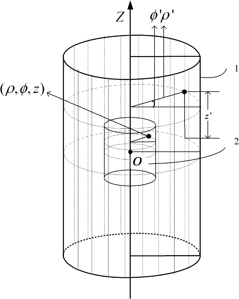
[0075] Such as figure 1 As shown, in the cylindrical coordinate system, the position of the transmitting and receiving antenna is (ρ′, φ′, z′), where ρ′ is the radius of the scanning aperture of the cylinder, φ′∈[0, 2π) is the azimuth of the antenna position, and the direction of φ′ It is defined as the azimuth direction, z' is the height of the antenna position, and the z' direction is defined as the height direction. In the cylindrical coordinate system, the scattering coefficient equation of the target area is I(ρ, φ, z), where ρ is the radius of the target position, φ is the azimuth of the target position, and z ...


PUM


Abstract

The invention discloses a three-dimensional microwave imaging method based on cylinder geometry, which relates to the microwave imaging technology. The three-dimensional microwave imaging method includes successively completing two-dimensional imaging on different cylinder surfaces by means of designing focusing functions corresponding to various imaging cylinder surfaces, and finally realizing three-dimensional imaging of a total objective region. The three-dimensional microwave imaging method avoids approximation in a processing process, main operations are carried out in a height wave number field and an orientation wave number field, interpolation is not required in a three-dimensional wave number field, and accordingly accurate and high-efficient three-dimensional imaging can be realized.

Description

technical field [0001] The invention relates to the technical field of microwave imaging, and is a three-dimensional microwave imaging method based on cylindrical geometry. Background technique [0002] Microwave imaging with 360° cylindrical scanning geometry can observe the target in all directions, and can realize high-resolution three-dimensional imaging of the target. Combined with the unique penetration characteristics of microwaves, microwave methods based on cylindrical scanning geometry are very suitable for imaging and detection of close-range hidden targets, such as: three-dimensional imaging of target surfaces, non-destructive testing, and diagnosis of target scattering characteristics. [0003] Correspondingly, microwave imaging methods based on this scanning geometry have been proposed one after another. M.Soumekh proposed a three-dimensional wavenumber domain method based on the Fourier decomposition of Green's function on the slanted plane (reference: M.Soum...

Claims


Application Information

Patent Timeline
IPC IPC(8): G01S13/89
Inventor 洪文王彦平谭维贤林贇吴一戎
Owner INST OF ELECTRONICS CHINESE ACAD OF SCI
Why Eureka
Try Eureka