Supercharge Your Innovation With Domain-Expert AI Agents!

Rotor structure for fault-tolerant permanent magnet motor

一种转子结构、永磁体的技术,应用在磁路形状/式样/结构、电动组件、磁路转动零部件等方向,能够解决增加增量成本、牺牲功率效率等问题

Active Publication Date: 2016-11-23
GE ENERGY POWER CONVERSION TECH
View PDF6 Cites 0 Cited by
  • Summary
  • Abstract
  • Description
  • Claims
  • Application Information

AI Technical Summary

Problems solved by technology

Therefore, such measures may sacrifice power efficiency and increase incremental cost

Method used


Image

  • Rotor structure for fault-tolerant permanent magnet motor
  • Rotor structure for fault-tolerant permanent magnet motor
  • Rotor structure for fault-tolerant permanent magnet motor

Examples


Embodiment Construction

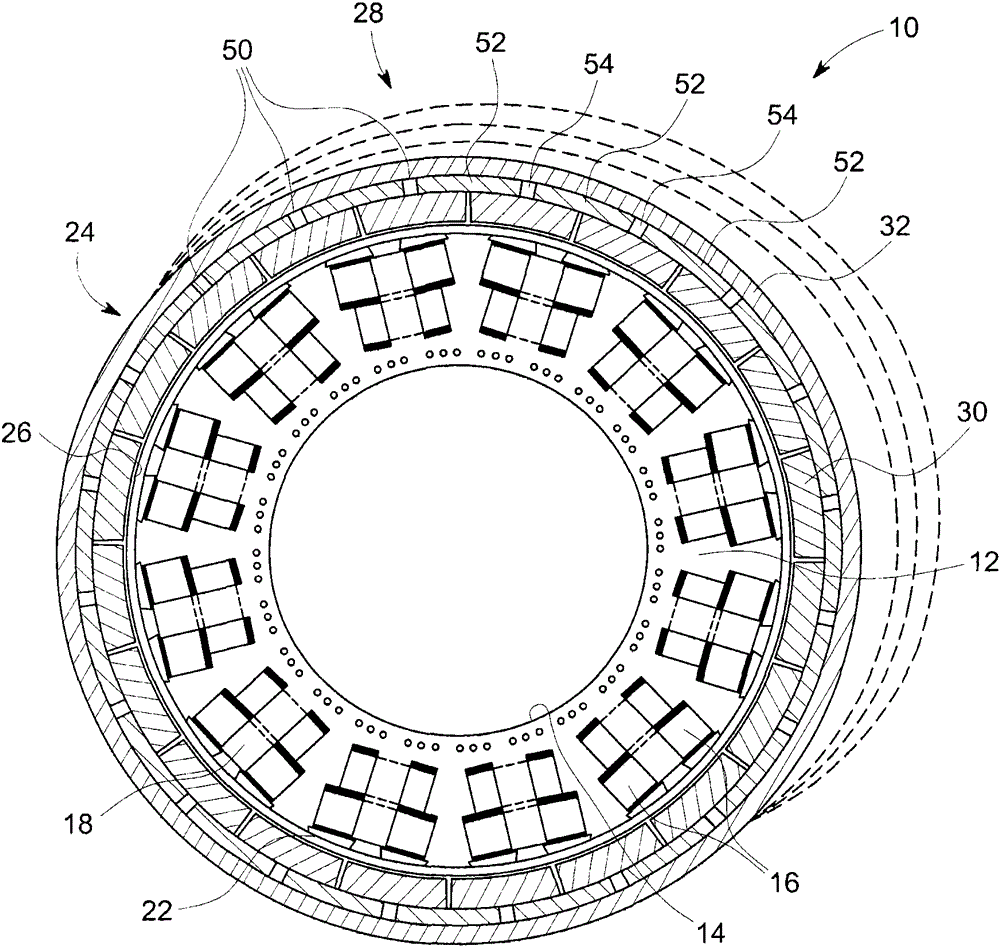
[0041] As discussed in more detail below, aspects of the present invention relate to fault-tolerant permanent magnet machines that may include fractional slot pitch concentrated windings. As used herein, the term "fault tolerance" refers to the magnetic separation and physical separation between various machine coils / phases, while reducing noise, torque ripple and harmonic flux components.

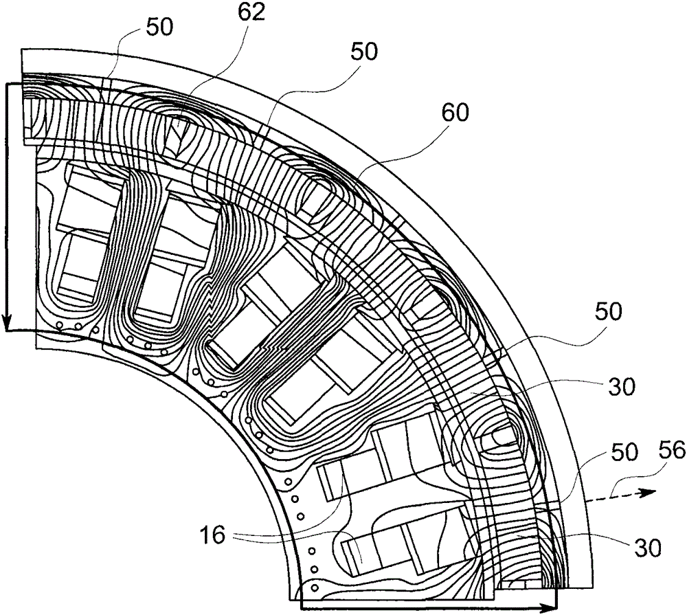
[0042] The inventors of the present invention propose an innovative and first-class method suitable for substantially reducing electromagnetic rotor losses generally associated with the frequency spectrum of the spatial harmonics of the fractional slot pitch concentrated winding. As mentioned before, this spectrum includes many asynchronous harmonics that do not add useful MMF. The proposed method can be advantageously configured to maximize the magnetoresistance encountered by asynchronous harmonics, while having substantially no effect on the useful or synchronous MMF components, thereby ma...


PUM


Abstract

The invention relates to a rotor structure for a fault-tolerant permanent magnet motor. A rotor structure (24) for a permanent magnet motor (10) is provided. A back core lamination (28) is disposed around a plurality of permanent magnets (30). The core lamination (28) includes a plurality of high reluctance regions (50) arranged to avoid synchronous magnetic flux components while attenuating asynchronous magnetic flux components. The asynchronous and synchronous flux components are generated by the space harmonic components of the multiple fractional slot concentrated windings (18) of the machine's stator (12).

Description

Technical field [0001] The present invention generally relates to permanent magnet (PM) motors, such as generators and / or electric motors, and more specifically, to fault-tolerant PM machines. Background technique [0002] It is known that due to electrical induction, a motor can use permanent magnets (PM) as the main mechanism to generate a high-amplitude magnetic field. Unlike machines that include electromagnets that can be electrically controlled (eg, selectively turned on or off), PM remains on. In other words, due to the inherent ferromagnetic properties of PM, the magnetic field produced by PM is permanent. Therefore, if a motor with PM experiences a failure, it may not be convenient to stop the machine because the permanent nature of the PM's magnetic field will cause the machine to continue to operate. Such failures may be in the form of fault currents due to defects in the stator windings or mechanical failures caused by defective or worn mechanical components provide...

Claims


Application Information

Patent Timeline
Patent Type & Authority Patents(China)
IPC IPC(8): H02K1/27H02K1/28
CPCH02K29/03H02K2213/12H02K1/2791
Inventor M·沙A·M·F·艾尔-雷菲
Owner GE ENERGY POWER CONVERSION TECH
Features
  • R&D
  • Intellectual Property
  • Life Sciences
  • Materials
  • Tech Scout
  • Unparalleled Data Quality
  • Higher Quality Content
  • 60% Fewer Hallucinations
Learn More