
Light-emitting diode (LED) illuminating system

A LED lighting and lighting system technology, applied in the field of LED lighting systems, can solve problems such as unstable work, narrow application range, and short control distance, and achieve the effects of avoiding work disorder, low cost, and stable control work

Inactive Publication Date: 2014-02-26
GUIZHOU XINGGUO NEW ENERGY TECH
View PDF4 Cites 1 Cited by
  • Summary
  • Abstract
  • Description
  • Claims
  • Application Information

AI Technical Summary

Problems solved by technology

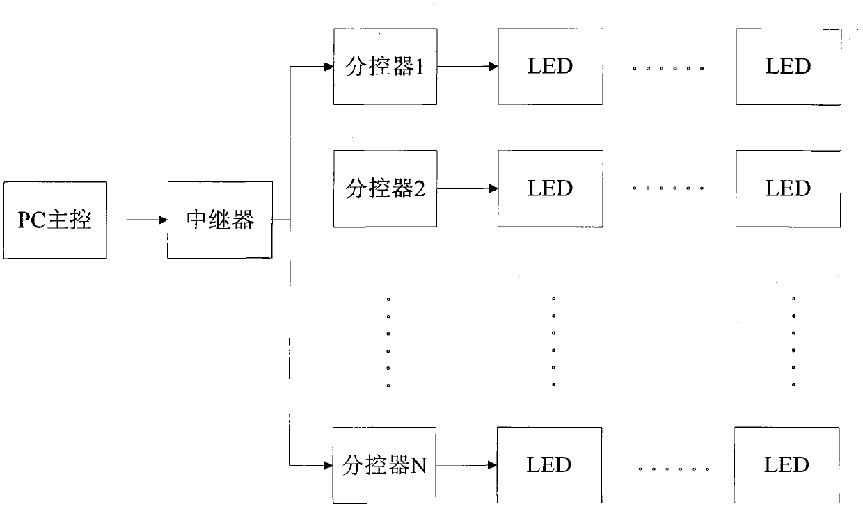
[0008] The purpose of the present invention is to solve technical problems such as short control distance, narrow application range, unstable operation and high cost in the lighting system of the LED lamp in the prior art. The present invention provides a new lighting system of the LED lamp

Method used


Image

  • Light-emitting diode (LED) illuminating system
  • Light-emitting diode (LED) illuminating system
  • Light-emitting diode (LED) illuminating system

Examples


Embodiment

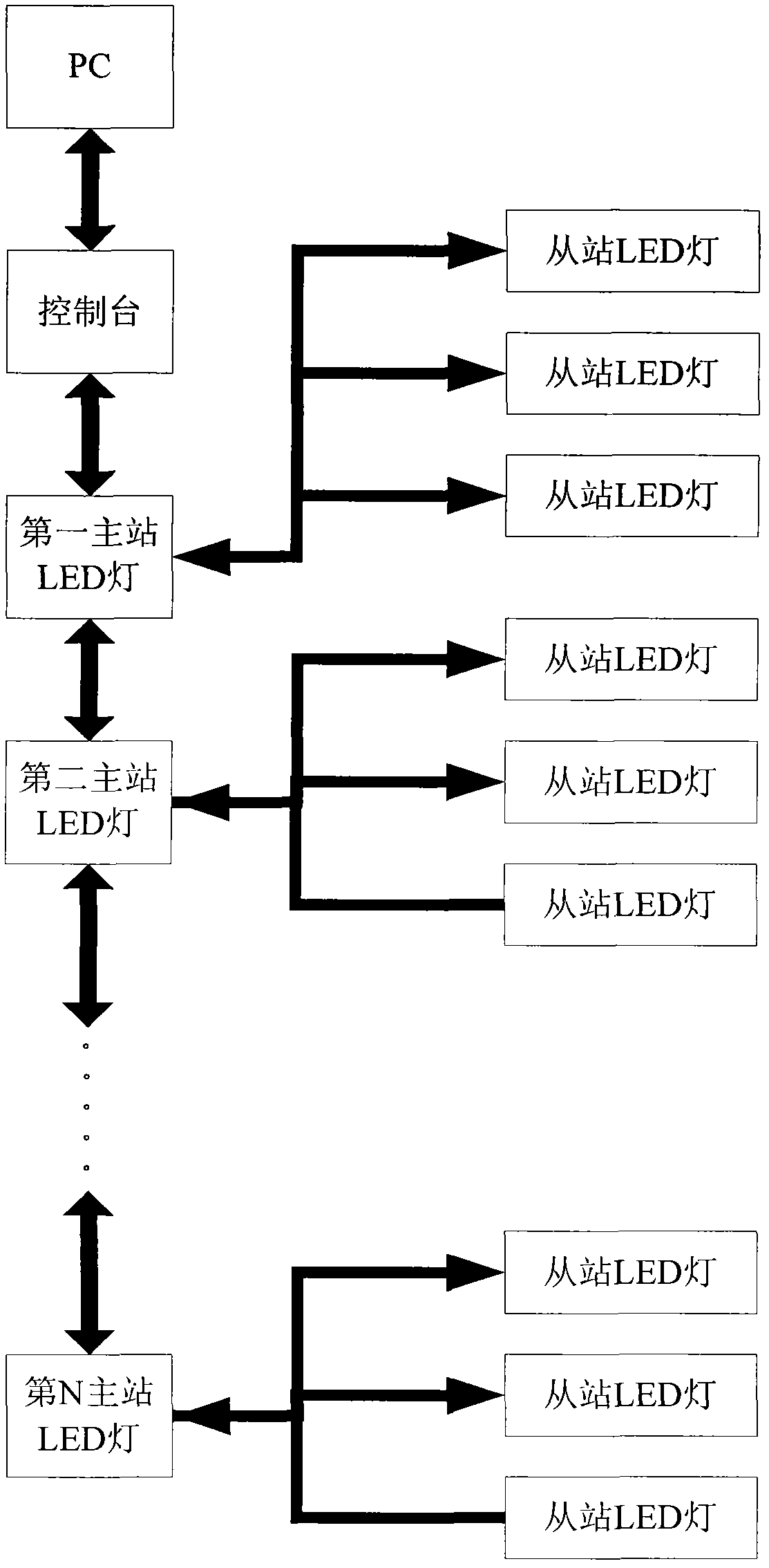
[0032] Such as figure 2 As shown, an LED lighting system provided by the present invention includes a console and a plurality of LED lamp groups, each LED lamp group includes a master station LED lamp and a plurality of slave station LED lamps, and the console and PC Connection, can adopt wireless connection, also can be connected by wired mode, described console, master station LED lamp and slave station LED lamp all comprise a radio frequency unit, in order to distinguish, in the present invention, the radio frequency unit of console, we It is called the first radio frequency unit, the radio frequency unit of the master station LED light is called the second radio frequency unit, and the radio frequency unit of the slave station LED light is called the third radio frequency unit. The slave stations in the same LED light group The LED light and the LED light of the main station are connected by the radio frequency signal of the second radio frequency unit and the third radio...


PUM


Abstract

An LED lighting system, including a console and a plurality of LED light groups, each LED light group including a main station LED light and a plurality of slave station LED lights. The slave station LED lights and the main station LED light in each LED light group establish radio frequency communication, and each main station LED light performs one-to-one ground relay radio frequency communication. The console performs radio frequency communication with a main station LED light, the main station LED light transmitting the radio frequency signal of the console to another main station LED light in relay. The console includes a first control unit, wherein the first control unit sends to the main station LED light an instruction controlling the operation of the main station LED light by way of the communication link established between the console and the main station LED light and sends to the slave station LED lights an instruction controlling the operation of the slave station LED lights by way of the communication link established between the console and the slave station LED lights. The LED lighting system has the advantages of a wide application range, stable performance and convenient maintenance.

Description

technical field [0001] The invention relates to a lighting device, in particular to an LED lighting system. Background technique [0002] With the promotion of the concept of low-carbon energy saving, LED lights have been widely used in the field of lighting. In the urban lighting project, LED guardrail tubes along the street, LED decorative lights on the walls of buildings and LED buried lights along the road need to use multiple LED lights or multiple LED light groups to form an LED that can be contrasted and coordinated with each other. The lighting system can have a very good visual and beautifying effect. Therefore, it is necessary to independently control each LED or each LED light group through a control system, and control its working status at any time, including on and off status, brightness and displayed color, etc. [0003] The current control methods for LED lighting systems include the following: [0004] 1. LED lighting system with wired control, such as f...

Claims


Application Information

Patent Timeline
Patent Type & Authority Patents(China)
IPC IPC(8): G08C17/02H05B37/02
CPCG08C17/02H05B37/02H05B37/0272H05B33/0845H05B45/10H05B47/19
Inventor 耿跃峰殷志锋葛瑜张广韬张元敏郭利辉王红玲王金
Owner GUIZHOU XINGGUO NEW ENERGY TECH
Learn More