

LED display system
A technology for display systems and LED lights, applied in signal transmission systems, static indicators, lighting devices, etc., can solve the problems of narrow application range, short control distance, unstable work, etc., achieve low cost, convenient maintenance, and realize automatic The effect of the control function
- Summary
- Abstract
- Description
- Claims
- Application Information
AI Technical Summary
Problems solved by technology
Method used
Image

Examples
Embodiment
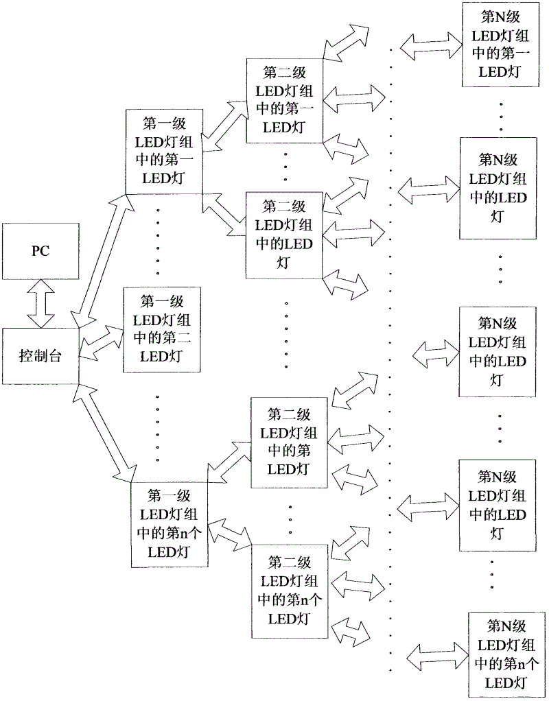
[0034] Such as figure 2 As shown, an LED display system provided by the present invention includes a console and a plurality of LED lamps, and the plurality of LED lamps are arranged in multi-level LED lamp groups, and each level of LED lamp groups includes multiple LED lamps, one LED lamp in the Nth class LED lamp group performs one-to-many radio frequency communication with each LED lamp in the N+1th class LED lamp group, and the console communicates with each LED lamp group in the first class LED lights perform one-to-many radio frequency communication, and N is a natural number. The console is connected to the PC, which can be connected wirelessly or by wire. The console, the LED lights of the master station and the LED lights of the slave station all include a radio frequency unit. In order to distinguish, in the present invention, the control The radio frequency unit of the station, we call it the first radio frequency unit, we call the radio frequency unit of the LED ...
PUM
 Abstract
Description
Claims
Application Information