Self-pressurization air inflation sealing butterfly valve

An inflatable sealing and self-pressurizing technology, which is applied in the field of sealing butterfly valves and self-pressurizing inflatable sealing butterfly valves, can solve problems such as operation and inability to operate remotely, and achieve the effects of prolonging service life, reliable shrinkage recovery, and uniform elastic deformation

Pending Publication Date: 2018-10-09
章锡明
View PDF0 Cites 5 Cited by
  • Summary
  • Abstract
  • Description
  • Claims
  • Application Information

AI Technical Summary

Problems solved by technology

And only need to pressurize the rubber sealing ring of the inflation valve by 0.1MP~0.3MPa higher than the medium pressure of the pipeline to realize the valve sealing; The conventional pressure of the source is less than 1.0MPa, and the working pressure of various gas circuit control solenoid valves is less than 1.0MPa, which means that the highest available inflation pressure level of the inflation valve can only reach 1.0MPa, and the sealing capacity of the valve is only 0.8MPa. It cannot operate on pipelines with higher pressure levels. Although it can be inflated by moving high-pressure gas sources (high-pressure gas cylinders, high-pressure gas storage tanks, etc.), it can only be limited to on-site manual inflation valves and cannot be operated remotely; therefore, such Due to the limitation of inflation pressure conditions, high-performance inflation valves cannot be fully promoted and widely used on a large scale in highly developed modern industrial automation control pipelines.

Method used


Image

  • Self-pressurization air inflation sealing butterfly valve
  • Self-pressurization air inflation sealing butterfly valve
  • Self-pressurization air inflation sealing butterfly valve

Examples


Embodiment Construction

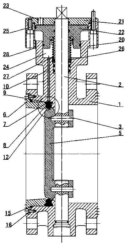
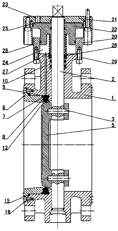
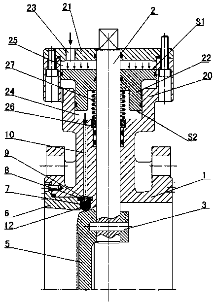
[0013] The invention relates to a self-pressurized air-tight sealing butterfly valve, such as figure 1 — Figure 5Said, including a valve body 1, valve shaft 2 is set in the valve body, the valve shaft is connected to the valve plate 5 through the pin 3, the inner port of the valve body 1 is provided with a sealing gland 6, and the sealing gland 6 is provided with a hollow The Ω-shaped pressure-charging rubber ring 7, the Ω-shaped pressure-charging rubber ring 7 is provided with a bar-shaped pressure-charging bracket 8, and a through-hole 9 is formed in the bar-shaped pressure-charging bracket, and the pressure-charging inner channel 10 is set in the wall of the valve body 1 , the pressurized inner channel 10 communicates with the through hole 9 to form a sealed cavity 4 in the Ω-shaped pressurized rubber ring 7, and the valve body 1 is provided with a self-pressurizing mechanism, and the self-pressurizing mechanism includes a valve shaft 2 as The center is provided with a bo...


PUM


Abstract

The invention provides a self-pressurization air inflation sealing butterfly valve. The self-pressurization air inflation sealing butterfly valve comprises a valve body valve plate, wherein a sealingpressing sleeve is arranged on the valve body, a hollow omega-shaped pressure filling rubber ring is arranged on the sealing pressing sleeve, a strip-shaped filling support and a through hole are formed in the omega-shaped filling rubber ring, a pressure filling inner channel is arranged in the wall of the valve body, and the pressure filling inner channel communicates with the through hole to form a sealing cavity in the omega-shaped pressure filling rubber ring, a pressurization cylinder body and a pressurization cylinder cover are arranged on the valve body by taking the valve shaft as thecenter, an air inlet is formed in the pressurization cylinder cover, a pressurizing piston is arranged in the pressurization cylinder body, and the area S1 of the upper end surface of the pressurizingpiston is larger than the area S2 of the lower end surface, a low-pressure cavity is formed between the pressurizing piston and the pressurization cylinder cover, a high-pressure cavity is formed between the pressurization piston and the valve body, hydraulic oil is injected into the high-pressure cavity, the high-pressure cavity communicates with the pressure filling inner channel, a spring seatis arranged on the valve shaft at the side of the high-pressure cavity, a reset spring is arranged on the spring seat, and the reset spring is in contact with the pressurization piston.

Description

technical field [0001] The invention relates to a sealed butterfly valve, in particular to a self-pressurized and inflated sealed butterfly valve, which belongs to the field of valves. Background technique [0002] Due to its compact structure, light and small size, convenient operation and excellent performance, butterfly valves are widely used in liquid, gas and gas powder co-transport pipeline control systems in various industries for opening and closing or regulating flow. In recent years, the inflatable butterfly valve has been widely used. By directly filling the air cavity of the hollow rubber sealing ring with air pressure, the rubber sealing ring will expand after inflation, so as to make up the gap between the wear and the sealing pair or wrap the inclusions, and act on the gap between the sealing pair. The seal can be realized by sealing the specific pressure, and the sealing characteristic is very ideal and very reliable. And only need to pressurize the rubber...

Claims


Application Information

Patent Timeline
Patent Type & Authority Applications(China)
IPC IPC(8): F16K1/228F15B3/00
CPCF16K1/2285F15B3/00
Inventor 章锡明陈卫东赵信恩
Owner 章锡明
Why Eureka
Try Eureka