
Spindle actuator

A technology for actuators and spindles, applied in the direction of non-mechanical drive clutches, clutches, transmissions, etc., can solve the problem of high cost

Inactive Publication Date: 2015-07-01
SCHAEFFLER TECH AG & CO KG
View PDF7 Cites 0 Cited by
  • Summary
  • Abstract
  • Description
  • Claims
  • Application Information

AI Technical Summary

Problems solved by technology

In order to be able to detect the load exerted by the spindle nut on the axially displaceable part, a correspondingly expensive sensor arrangement is necessary

Method used


Image

  • Spindle actuator
  • Spindle actuator
  • Spindle actuator

Examples


Embodiment Construction

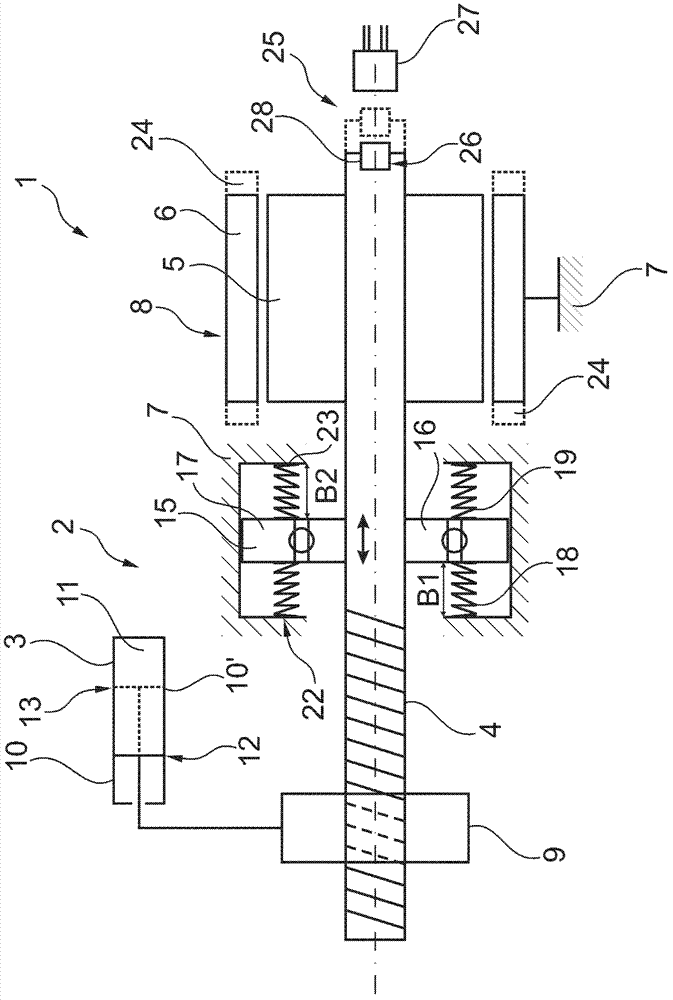
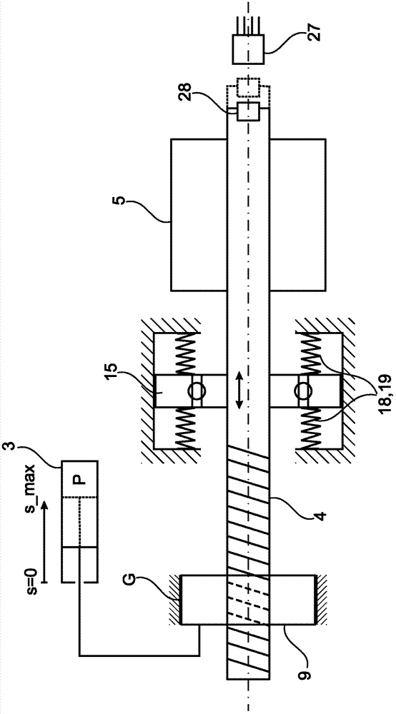
[0025] Figure 1A A spindle actuator 1 is shown schematically, here a hydrostatic actuator 2 with a master cylinder 3 which is connected via a pressure line to a slave cylinder, not shown. The spindle actuator 1 comprises a lead screw 4 driven by a rotor 5 of an electric motor 8 with its stator 6 arranged fixed to the housing on a housing 7 shown only in section. The lead screw 4 is now movable together with the motor bearing 15 described in detail below. The lead screw nut 9 is arranged on the lead screw 4 so as to be relatively rotatable, and the lead screw nut 9 is movably mounted on the housing 7 without relative torsion. The screw 4 and the screw nut 9 can be configured as a simple screw drive, a spherical screw drive or the like. The spindle and spindle nut can also be designed as a planetary rolling gear.

[0026] The lead screw nut 9 is axially fixedly connected with the piston 10 of the active cylinder 3, and when the electric motor 8 drives the lead screw 4, the le...


PUM


Abstract

The invention relates to a spindle actuator (1), in particular for acting on a piston (10) of a master cylinder (3), comprising a housing (7), a threaded spindle (4) rotatably arranged on the housing, a spindle nut (9) arranged rotatably on the threaded spindle and in a rotationally-fixed manner relative to the housing, and an electric motor (8) that is accommodated in the housing and that drives the threaded spindle, the electric motor having a stator (6) and a rotor (5) rigidly connected to the threaded spindle and a sensor device (25) for detecting a load applied by the spindle nut to a component axially displaced by the spindle nut. In order to be able to determine the load applied by the threaded spindle to the axially displaced component if the load resistance is known, the threaded spindle is supported in a such a way that the threaded spindle can be axially displaced to a limited extent relative to the housing against the effect of at least one axially effective energy accumulator (18, 19), and an axial travel (B1, B2) of the threaded spindle is detected by means of the sensor device.

Description

technical field [0001] The invention relates to a spindle actuator, in particular for loading the piston of a master cylinder, said spindle actuator having a housing, a threaded screw mounted rotatably on said housing, on said threaded spindle A screw nut that can be twisted and arranged in a non-rotatable manner relative to the housing and an electric motor housed in the housing and driving the screw, the electric motor has a stator and a rotor and a sensor device, the rotor and The lead screw is fixedly connected, and the sensor device is used to detect the load exerted by the lead screw nut on a part axially moved by the lead screw nut. Background technique [0002] This type of spindle actuator is used as a drive with a transmission, wherein the screw, in particular a ball screw, is driven by an electric motor with a rotary drive, the screw nut is moved axially by a Components such as the master cylinder piston of a hydrostatic actuator that operates a friction clutch o...

Claims


Application Information

Patent Timeline
Patent Type & Authority Patents(China)
IPC IPC(8): F16H25/20F16H63/30
CPCF16H2025/2075F16D29/005F16H25/2021
Inventor J·格哈特M·格拉曼
Owner SCHAEFFLER TECH AG & CO KG
Learn More