Safety door device of cage

A technology of safety doors and cages, applied in transportation and packaging, lifting equipment in mines, etc., can solve the problems of difficult maintenance, inconvenient disassembly, and inconvenient use, etc., and achieve the effect of simple structure, convenient installation, and simple production

Inactive Publication Date: 2014-02-12
JIANGXI RARE EARTH & RARE METALS TUNGSTEN GRP
View PDF7 Cites 0 Cited by
  • Summary
  • Abstract
  • Description
  • Claims
  • Application Information

AI Technical Summary

Problems solved by technology

[0003] However, in the prior art, the safety doors in the cage generally adopt slider-type and scissor-type safety doors. The problem in the prior art is that the crossbar is not comfortable to move up and down, and it is not convenient to use; in addition, the structure is complicated. , it is inconvenient to disassemble and difficult to maintain

Method used


Image

  • Safety door device of cage
  • Safety door device of cage
  • Safety door device of cage

Examples


Embodiment Construction

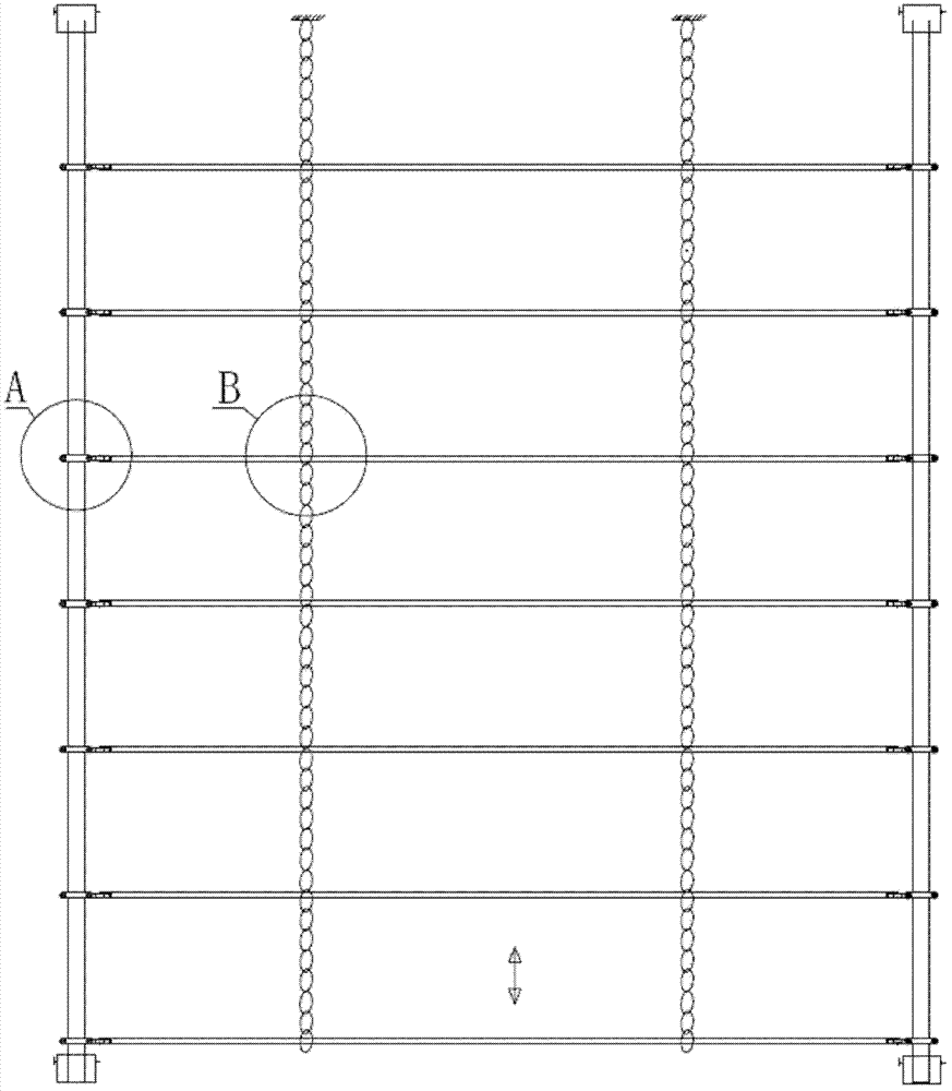
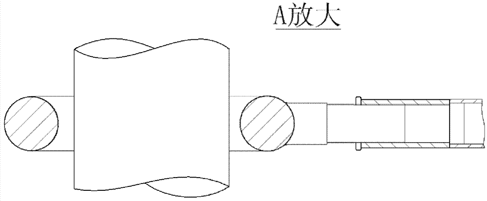
[0020] The structure and installation process of the cage safety door device according to the present invention will be described below in conjunction with the accompanying drawings.

[0021] In the accompanying drawings, reference numeral 1 represents a vertical rod; reference numeral 2 represents a chain; reference numeral 3 represents a cross bar; reference numeral 4 represents a ring; reference numeral 5 represents a connecting screw; Tight nut; reference numeral 7 represents the first positioning seat of the chain; reference numeral 8 represents the bolt; reference numeral 9 represents the nut; reference numeral 10 represents the pole positioning seat; and reference numeral 11 represents the second chain positioning seat.

[0022] Such as Figure 1-4 As shown, at first, the connecting screw 5 on the ring 4 is screwed into the internal thread on the cross bar 3, and tightened with the tightening nut 6, the first positioning seat 7 of the chain is installed, so that the cro...


PUM


Abstract

A safety door device of a cage comprises two vertical rods (1) and a series of transverse rods (3) which are parallel to each other and capable of moving vertically relative to the vertical rods (1). The safety door device of the cage is characterized in that two ends of each transverse rod (3) are provided with rings (4). Every two rings (4) are respectively sleeved on the vertical rods (1) at intervals to enable the transverse rods (3) to be capable of sliding vertically along the vertical rods (1). Two ends of each transverse rod (3) are provided with inner threads, and the transverse rods (3) are matched with connection crews (5) on the rings (4) through the inner threads. Each transverse rod (3) is connected with at least one chain (2), the upper end of the chain (2) is connected with a chain second location seat (11) arranged on a ceiling of the safety door device of the cage through bolts, and the upper end and the lower end of each vertical rod are respectively provided with a vertical rod location seat (10). The safety door device has the advantages of being simple in structure, convenient to disassemble, easy to maintain and convenient to use. The transverse rods vertically move freely.

Description

technical field [0001] The invention relates to a cage safety door device, which belongs to the field of mining machinery and equipment. Background technique [0002] In mining operations, cage devices are often used as transportation equipment, wherein the safety doors in the cage devices generally include vertical bars and cross bars, and the cross bars can move along the vertical bars to realize the opening or closing of the safety doors to facilitate entry and exit. [0003] However, in the prior art, the safety doors in the cage generally adopt slider-type and scissor-type safety doors. The problem in the prior art is that the crossbar is not comfortable to move up and down, and it is not convenient to use; in addition, the structure is complicated. , It is inconvenient to disassemble, and the difficulty of maintenance is relatively large. Contents of the invention [0004] The object of the present invention is to provide a cage safety door device, which has simple ...

Claims


Application Information

Patent Timeline
Patent Type & Authority Patents(China)
IPC IPC(8): B66B17/36
Inventor 周辉民罗正发张秋才彭希群朱勤朴
Owner JIANGXI RARE EARTH & RARE METALS TUNGSTEN GRP
Why Eureka
Try Eureka